Application Instruction for Single-Ended and Differential Microphones
1. Introduction
1.1 Background and Objectives
Chipintelli voice chips support differential microphones with differential circuit designs, and single-ended microphones with single-ended circuit designs. In practice, mismatched pairings may occur. This document explains the two circuit designs to help prevent incorrect pairings and guide proper usage.
2. Microphone Hardware Circuit Design
2.1 Differential Circuit Design for CI-130X Series
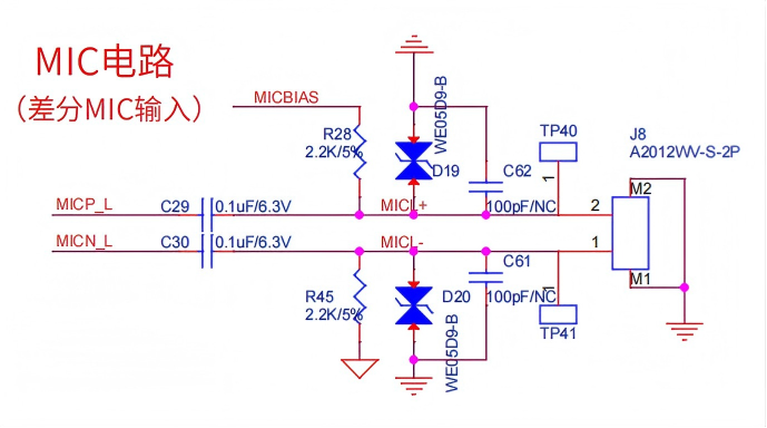
(Differential) MIC Circuit Design Notes:
- If the application solution does not require EMC testing, then C61 and C62 can be left unpopulated (NC).

PCB Design Requirements:
Default component layer is TOP layer.
1. When routing the PCB, design the MIC trace first. Ensure the trace is smooth and the length is minimized.
2. Keep MIC circuit traces away from other signal traces. All traces must be routed on the TOP layer without layer changes.
3. Enclose both sides of the MIC trace with AGND. For multi-layer boards, ensure the BOTTOM layer opposite the MIC circuit unit has a solid AGND copper pour. No other signal traces should pass through the entire AGND copper area.
4. Place D19 and D20 close to the interface connector.
2.2 Single-Ended Circuit Design for CI-130X Series
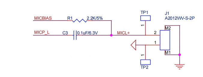
The single-ended MIC input design of this solution can only be selected under the following application conditions:

1. The application environment has no electromagnetic interference sources or noise interference sources.
2. The total length of the microphone input line does not exceed 20 centimeters.
3. The standard software default configuration for MIC is set to differential input mode. When using a single-ended input for MIC, software configuration changes are required. For specific configuration methods, please refer to the latest version of the design guide document **"!!!Important Readme!!!.pdf"**.

PCB Design Requirements:
Default component layer is TOP layer.
1. When routing the PCB, design the MIC trace first. The routing should be smooth and the trace length minimized.
2. MIC circuit traces must be kept away from other signal traces. All routing must be done on the TOP layer without changing layers.
3. Enclose both sides of the MIC trace with AGND. For multi-layer boards, ensure the BOTTOM layer opposite the MIC circuit unit has a solid AGND copper pour. No other signal traces should pass through the entire AGND copper area.
4. If the PCB is a single-layer board, connect AGND to DGND with the shortest possible trace.
2.3 Differential Circuit Design for CI-13LC Series
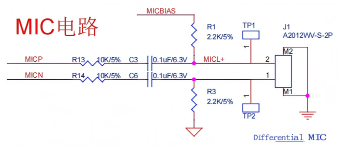
Circuit Design Note
1. The microphone input resistors R13/R14 can enhance the microphone's ESD resistance.
2. After adding these resistors, ESD protection devices are generally not required in common application scenarios.
3. For high-reliability applications, it is recommended to add ESD protection devices.
4. If using a shielded cable microphone, adopt single-ended input configuration: R14 = NC, C6 = NC, R3 = 0R.

PCB Design Requirements
1. Prioritize MIC trace routing, ensuring it is as short as possible.
2. Keep MIC circuit traces away from other traces. MIC traces must be routed on the top layer without switching layers.
3. Place a solid AGND pour on the bottom layer under the MIC circuit. Enclose both sides of the MIC traces with AGND, ensuring a complete AGND area on the bottom layer.
2.4 Single-Ended Circuit Design for CI-13LC Series
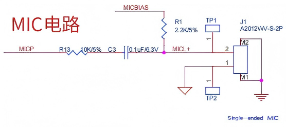
Circuit Design Note
1. The microphone input resistor R13 can improve the microphone's electrostatic discharge (ESD) protection capability.
2. After adding this resistor, ESD protection devices can generally be omitted in common application scenarios.
3. For applications with high reliability requirements, it is recommended to add ESD protection devices.

PCB Design Requirements
1. Prioritize MIC trace routing, ensuring it is as short as possible.
2. Keep MIC circuit traces away from other traces. MIC traces must be routed on the top layer without layer changes.
3. Pour AGND on the bottom layer under the MIC circuit. Enclose both sides of the MIC traces with AGND, ensuring a complete AGND area on the bottom layer.
3. Usage Notes for Single-Ended vs Differential Microphones
3.1 Signal Transmission Methods
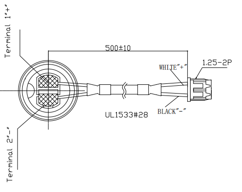
A single-ended microphone transmits audio over a single signal wire, typically wrapped by a metallic shield (e.g., copper mesh or aluminum foil). After grounding, the shield blocks external electromagnetic interference (EMI). The shield is usually connected to signal ground, forming a single-ended grounded structure, as shown in Figure 1.
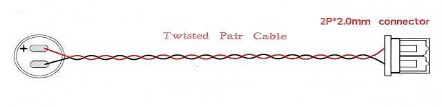
A differential microphone uses two signal wires, positive (+) and negative (−), carrying opposite-phase signals. It does not rely on shielding for anti-interference; instead, twisted-pair differential signaling cancels common-mode noise, as shown in Figure 2.
3.2 Electromagnetic Immunity Comparison
| Feature | Single-Ended Microphone | Differential Microphone |
|---|---|---|
| EMI immunity | Relies on shield braid to block external interference | Cancels interference via differential signaling; does not rely on shielding |
| Common-mode noise rejection | Weaker (noise directly adds to the single-ended signal) | Very strong (common-mode noise is suppressed by differential signaling) |
| Ground noise suppression | Shield can reduce ground-loop interference but cannot eliminate it | Immune to ground noise (two signal lines with floating reference) |
3.3 Impact of Incorrect Microphone-to-Circuit Pairing
3.3.1 Differential Microphone Used with a Single-Ended Circuit
Typically, the impact is small. Under the same conditions, recognition accuracy is close to that of the correct pairing.
3.3.2 Single-Ended Microphone Used with a Differential Circuit
This may affect recognition accuracy, because EMI on the shield can couple through the microphone negative terminal directly into the chip input pin.
4. Microphone Component Selection
For our voice chips, two microphone parameters are critical: sensitivity must be −32 ± 3 dB, and signal-to-noise ratio (SNR) must be ≥ 65 dB. We recommend adopting our validated microphone designs directly. Refer to our Peripheral Component Compatibility List to select appropriate microphones.