引脚描述
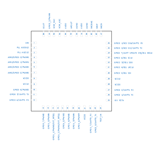
CI1122芯片引脚图如图2所示:

图2 CI1122芯片引脚图
芯片各个引脚功能如下表描述:
表2 芯片引脚功能描述
| Pin Number | Pin name | Pin type | IO driving capability | IO power-on default state | Alternate functions |
|---|---|---|---|---|---|
| 1 | XIN | I | - | - | 12.288MHZ crystal oscillator interface |
| 2 | PLL_AVDD12 | P | - | - | PLL 1.2V power supply |
| 3 | PLL_AVSS12 | P | - | - | PLL ground |
| 4 | AIN0 | IO | 4mA | IN,T+D | Default:ADC0 Input Can be configured as Digital functions pin. 1.GPIO0_0 2.PWM0 Output |
| 5 | AIN1 | IO | 4mA | IN,T+D | Default:ADC1 Input Can be configured as Digital functions pin. 1.GPIO0_1 2.PWM1 Output |
| 6 | AIN2 | IO | 4mA | IN,T+D | Default:ADC2 Input Can be configured as Digital functions pin. 1.GPIO0_2 2.PWM2 Output |
| 7 | AIN3 | IO | 4mA | IN,T+D | Default:ADC3 Input Can be configured as Digital functions pin. 1.GPIO0_3 2.PWM3 Output |
| 8 | VCC33 | P | - | - | 3.3V power supply |
| 9 | VCC12 | P | - | - | 1.2V Core power supply |
| 10 | GPIO0_4 | IO | 4mA | IN,T+D | 1.GPIO0_4 2.PWM2 Output |
| 11 | GPIO0_5 | IO | 4mA | IN,T+U | 1.Reserved 2.GPIO0_5 3.UART1_TX |
| 12 | GPIO0_6 | IO | 4mA | IN,T+D | 1.Reserved 2.GPIO0_6 3.UART1_RX |
| 13 | GPIO0_7 | IO | 4mA | IN,T+U | 1.Reserved 2.GPIO0_7 3.PWM3 |
| 14 | GPIO1_0 | IO | 4mA | IN,T+D | 1.Reserved 2.GPIO1_0 3.PWM4 |
| 15 | PWM0 | IO | 4mA | IN,T+D | 1.GPIO1_1 2.PWM0 Output 3.EXT_INT[0] |
| 16 | PWM1 | IO | 4mA | IN,T+D | 1.GPIO1_2 2.PWM1 Output 3.EXT_INT[1] |
| 17 | PWM2 | IO | 4mA | IN,T+D | 1.GPIO1_3 2.PWM2 Output |
| 18 | PWM3 | IO | 4mA | IN,T+D | 1.GPIO1_4 2.PWM3 Output |
| 19 | PWM4 | IO | 4mA | IN,T+D | 1.GPIO1_5 2.PWM4 Output |
| 20 | PWM5 | IO | 4mA | IN,T+D | 1.GPIO1_6 2.PWM5 Output |
| 21 | VCC33 | P | - | - | 3.3V power supply |
| 22 | UART0_RX | IO | 4mA | IN,T+U | 1.GPIO1_7 2.UART0_RX: Receive channel of UART0 |
| 23 | UART0_TX | IO | 4mA | IN,T+U | 1.GPIO2_0 2.UART0_TX: Transmit channel of UART0 |
| 24 | TEST_EN | I | - | - | Internal pull-down 0—functional mode 1—TEST mode |
| 25 | KEY_RSTn | I | - | - | External reset input. Pull this pin low to reset device to initial state. Has internal weak pull-up. |
| 26 | UART1_TX | IO | 4mA | IN,T+U | 1.GPIO2_1 2.UART1_TX: Transmit channel of UART1 |
| 27 | UART1_RX | IO | 4mA | IN,T+U | 1.GPIO2_2 2.UART1_RX: Receive channel of UART1 |
| 28 | VCC33 | P | - | - | 3.3V power supply |
| 29 | VCC12 | P | - | - | 1.2V Core power supply |
| 30 | IIS1_SDI | IO | 4mA | IN,T+D | 1.GPIO2_3 2.IIS1_SDI: Serial Data Input for IIS1 interface |
| 31 | IIS1_LRCLK | IO | 4mA | IN,T+D | 1.GPIO2_4 2.IIS1_LRCLK: IIS1 interface LRCLK clock |
| 32 | IIS1_SDO | IO | 4mA | IN,T+D | 1.GPIO2_5 2.IIS1_SDO: Serial Data Output for IIS1 interface |
| 33 | IIS1_SCLK | IO | 4mA | IN,T+D | 1.GPIO2_6 2.IIS1_SCLK: Serial Clock for IIS1 interface |
| 34 | IIS1_MCLK | IO | 4mA | IN,T+D | 1.GPIO2_7(UART_UPDATE_EN) At start-up, this pin is used to select one of two functional modes: 1—Start serial port upgrade service and program 0—Start directly from Flash 2.IIS1_MCLK:Master Clock for IIS1 reference |
| 35 | IIC0_SCL | IO | 4mA | IN,T+U | 1.GPIO3_0 2.IIC0_SCL: IIC0 Serial Clock 3.UART1_TX |
| 36 | IIC0_SDA | IO | 4mA | IN,T+U | 1.GPIO3_1 2.IIC0_SDA: IIC0 Serial Data 3.UART1_RX |
| 37 | MICN | I | - | - | Microphone N input |
| 38 | MICP | I | - | - | Microphone P input |
| 39 | MICBIAS | O | - | - | Microphone bias output |
| 40 | AGND | P | - | - | Analog ground |
| 41 | AVDD | P | - | - | 3.3V analog supply |
| 42 | AGND | P | - | - | Analog ground |
| 43 | HPOUT | O | - | - | DAC output |
| 44 | AVDD | P | - | - | 3.3V analog supply |
| 45 | VCM_ADC | O | - | - | ADC VCM output |
| 46 | VCM_DAC | O | - | DAC VCM output | |
| 47 | GPIO3_2 | IO | 4mA | IN,T+D | 1.GPIO3_2 2.PWM4 Output |
| 48 | XOUT | O | - | - | 12.288MHZ crystal oscillator interface |
上表中 IO引脚的状态定义如下:
I 输入
O 输出
IO 双向
P 电源或地
T+D 三态正下拉
T+U 三态正上拉
OUT 上电默认为输出模式
IN 上电默认为输入模式