CI230X SRRC Certification Test Method
Test environment construction
Hardware test preparation
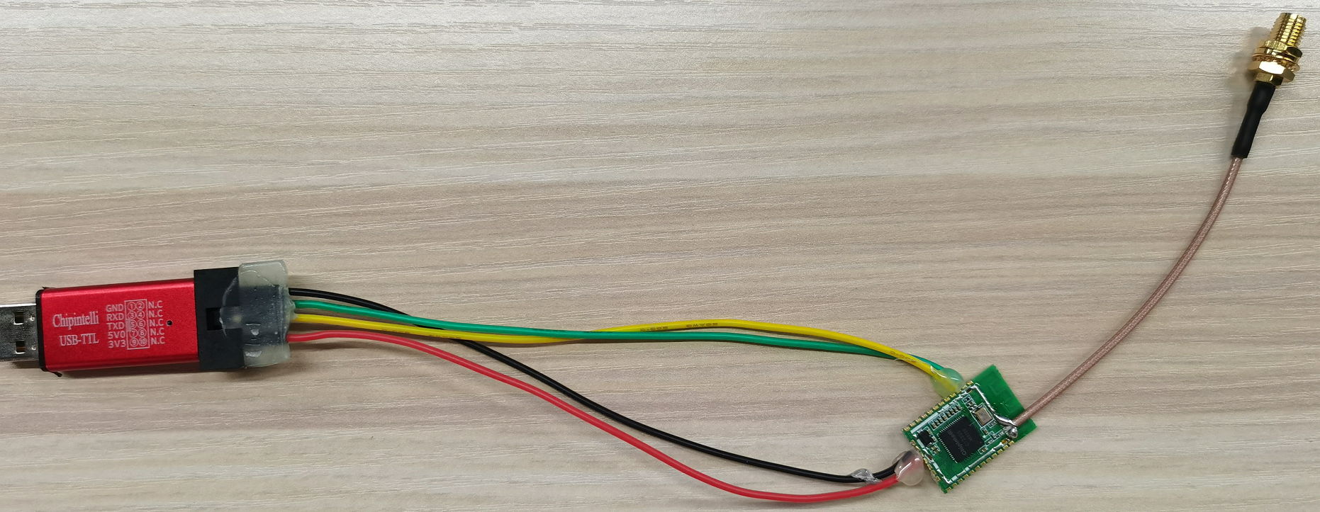
◆ The DUT to be tested is a module or development board based on CI230X chip.
◆ Connect serial port tools 3.3V, GND, UART-TX and UART-RX to modules VDD33, GND, PE2 and PE3.
◆ During the test, the PC sends the corresponding ATE test command, and the PC interacts with the DUT through UART to configure various test modes.
◆ Prepare 5 PCS of modules, 4 of which disconnect the antenna and matching circuit and weld the RF test line without shielding cover; 1 PCS with shield cover is a complete sample.
◆ Open the serial port tool, SSCOM is recommended, and check “Add Return and Line Feed“. Set the baud rate to 115200, select the corresponding COM port, and then configure the test command according to the subsequent commands in this article to test each mode.
◆ USB to serial port tool
◆ Several DuPont lines
Software test preparation
◆ Burn test firmware: Burn CI230X Fixed Frequency Test Firmware for basic fixed frequency test.
◆ Installation of USB to serial tool drive: ensure that the serial port drive has been correctly followed. If the serial port cannot be identified, it is recommended to install the USB to serial tool chip by yourself.
Constant frequency test
Wi-Fi fixed frequency test
| Command | Effect |
|---|---|
| Set duty cycle | |
| AT+PVTCMD=evm_tx_interval 100 | Set the duty cycle before issuing other AT commands |
| TX Send command | |
| AT+PVTCMD=EVM,TX,B,1,1,1000 | Send:11B 1M CH1 |
| AT+PVTCMD=EVM,TX,B,1,7,1000 | Send:11B 1M CH7 |
| AT+PVTCMD=EVM,TX,B,1,13,1000 | Send:11B 1M CH13 |
| AT+PVTCMD=EVM,TX,G,6,1,1000 | Send:11G 6M CH1 |
| AT+PVTCMD=EVM,TX,G,6,7,1000 | Send:11G 6M CH7 |
| AT+PVTCMD=EVM,TX,G,6,13,1000 | Send:11G 6M CH13 |
| AT+PVTCMD=EVM,TX,G,54,1,1000 | Send:11G 54M CH1 |
| AT+PVTCMD=EVM,TX,G,54,7,1000 | Send:11G 54M CH7 |
| AT+PVTCMD=EVM,TX,G,54,13,1000 | Send:11G 54M CH13 |
| AT+PVTCMD=EVM,TX,N,0,1,1000 | Send:11N MCS0 CH1 |
| AT+PVTCMD=EVM,TX,N,0,7,1000 | Send:11N MCS0 CH7 |
| AT+PVTCMD=EVM,TX,N,0,13,1000 | Send:11N MCS0 CH13 |
| AT+PVTCMD=EVM,TX,N,7,1,1000 | Send:11N MCS7 CH1 |
| AT+PVTCMD=EVM,TX,N,7,7,1000 | Send:11N MCS7 CH7 |
| AT+PVTCMD=EVM,TX,N,7,13,1000 | Send:11N MCS7 CH13 |
| RX Receive instructions | |
| AT+PVTCMD=EVM,RX,1 | Receive:CH1 |
| AT+PVTCMD=EVM,RX,7 | Receive:CH7 |
| AT+PVTCMD=EVM,RX,13 | Receive:CH13 |
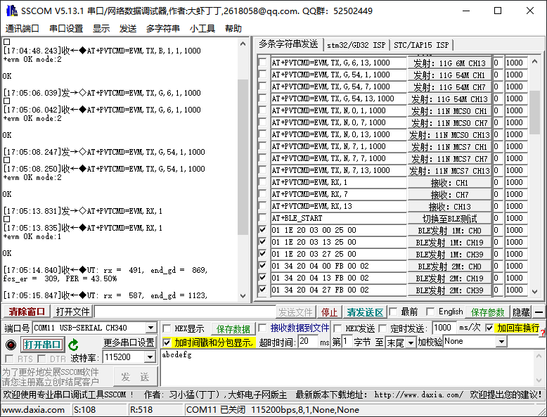
Wi-Fi command execution effect is as follows:
Bluetooth fixed frequency test
The Bluetooth fixed frequency test must be switched to the Bluetooth mode first. The command is as follows:
| Command | Effect |
|---|---|
| AT+BLE_START | Switch to BLE test |
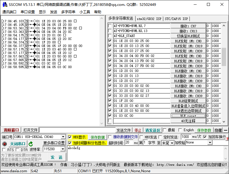
The execution effect of switching to Bluetooth command is as follows:
After switching to Bluetooth test, check “HEX display(HEX 显示)” and “HEX send(HEX 发送)”, the command is as follows:
| Command | Effect |
|---|---|
| 01 1E 20 03 00 25 00 | BLE_Send 1M(00 → CH0,13 → CH19,27 → CH39) |
| 01 34 20 04 00 FB 00 02 | BLE_Send 2M(00 → CH0,13 → CH19,27 → CH39) |
| 01 1D 20 01 00 | BLE_Receive 1M(00 → CH0,13 → CH19,27 → CH39) |
| 01 33 20 03 00 02 00 | BLE_Receive 2M(00 → CH0,13 → CH19,27 → CH39) |
| 01 1F 20 00 | BLE_End Test |
| 01 1E 20 03 40 00 00 | BLE_Prepare to enter the sideband test |
| 01 1E 20 03 50 00 00 | BLE_Exit sideband test |
| 01 03 0C 00 | BLE_reset |
The execution effect of Bluetooth command is as follows:
Supplementary notes
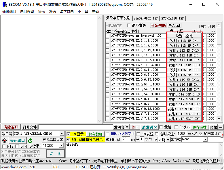
All the instructions described in this article have been configured in the SSCOM software provided with this article. When using, please open the “Extension” button and click the corresponding commands as required.
The SSCOM command is shown as follows


