Instructions for use of the recording board
Overview
In the process of debugging recognition and optimizing recognition effect, it is necessary to record the voice input of the microphone, analyze whether the bottom noise of the voice recognition module is normal, and whether the microphone voice input has abnormal interference from outside. To solve this problem, you can use a recording board to collect audio from the module, and analyze the collected audio to determine whether there is noise or interference. The following content describes how to use the recording board to collect audio from the module. If the user wants to obtain the audio recording board, please click batch purchase Purchase or contact our business personnel.
Required equipment and components
-
A computer.
-
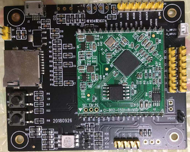
A set of speech recognition module boards, as shown in Figure 1, is the CI-B02CS01S development kit (this module is used for document examples, and the recording board is applicable to all speech recognition modules).
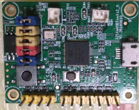
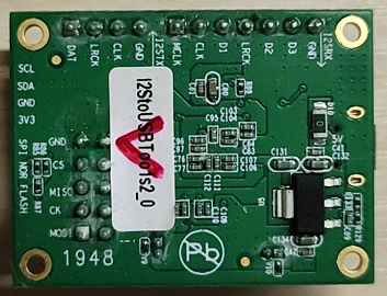
- A recording board, as shown in Figure 2.
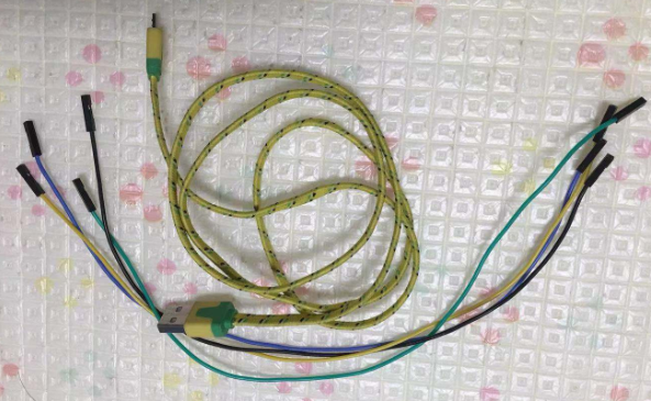
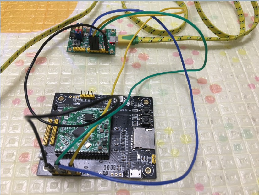
- One Micro USB cable and several DuPont cables, as shown in Figure 3.
- Audio acquisition software.
Note: Audio acquisition software should be installed on the computer first
Operating Steps
Connect the voice recognition module board and the recording board
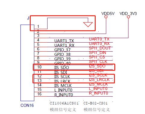
Connect the voice recognition module board and the recording board with DuPont cable. This document takes the CI-B02CS01S module as an example, as shown in Figure 4 below, several pins need to be connected on the schematic diagram of CI-B02CS01S, and Figure 5 is the corresponding pin of the recording board. The other two modules need to be grounded together.
The specific wiring relationship between the voice recognition module and the recording board module is as follows, and the complete wiring diagram is shown in Figure 6.
Speech recognition module pin —>Recording board module pin
IISCLK —> CLK
IISLRCLK —> LRCLK
llSSDO —> DI
GND —> GND
#Recording board connected to computer
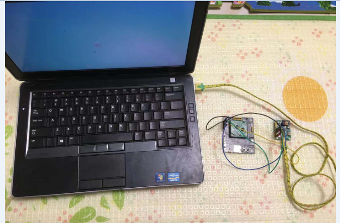
The recording board is connected to the computer through the Micro USB cable, as shown in Figure 7 below. Under normal circumstances, the Windows system has a built-in device driver, which can directly support the plug and play of the recording board. If the computer prompts you to install the driver, please find the corresponding driver for installation or contact our technicians for support.
Configure the computer recording device as the recording board microphone
Configure the microphone input of the recording board in the computer recording equipment. The specific steps are as follows:
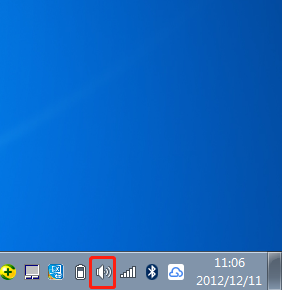
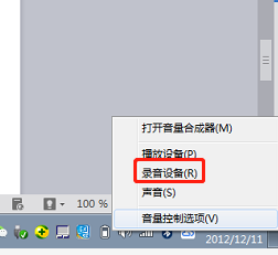
- Right click the sound device in the lower right corner of the computer, as shown in Figure 8.
- The interface pops up as shown in Figure 9. Select the recording device.
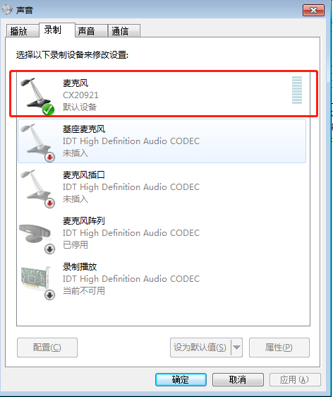
- Pop up the sound input device, as shown in Figure 10.
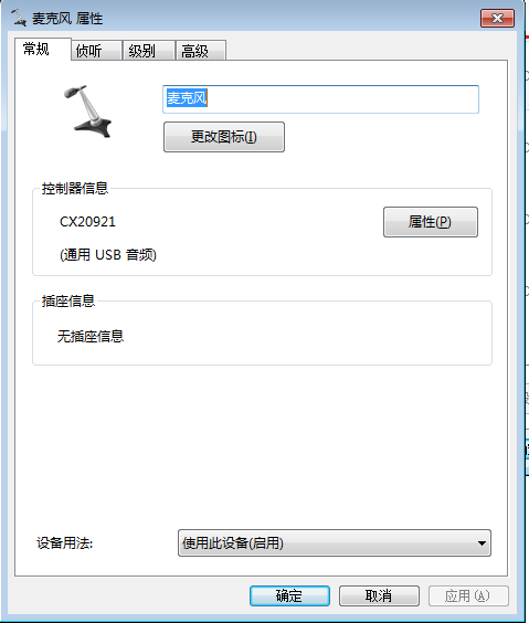
- Double click the CX20921 microphone device in Figure 10, and the interface shown in Figure 11 pops up.
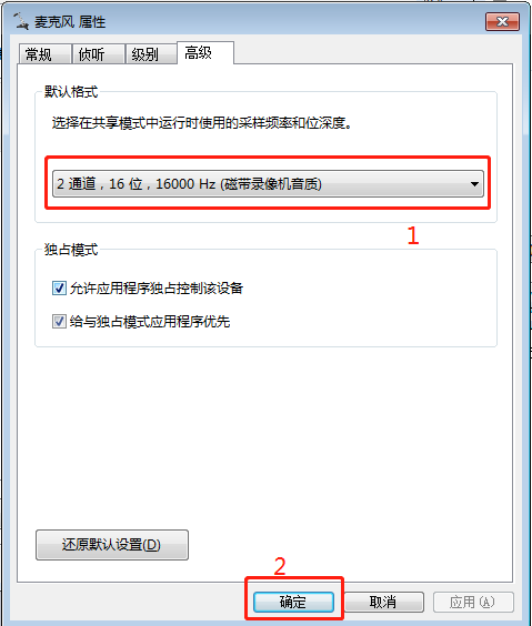
- Select the advanced options in Figure 11 and the corresponding audio sampling format, as shown in Figure 12.
- Click Apply and OK to exit the setting. You can open the audio capture software to start recording.
Special reminder
- When designing the module PCB, please reserve IIS test points to facilitate the bottom noise analysis after recording;
- After the module bottom noise test is normal, if there are still problems identified, the test recording under the whole machine status can be collected and sent to Chipintelli technical support personnel for analysis and optimization.
