Automated Speech Recognition Test
Under normal circumstances, speech recognition testing is time-consuming, and multiple rounds of testing are often required during product development. Traditional manual testing methods are inefficient and prolong the cycle from development to mass production. Therefore, our company has developed an automated speech recognition testing methodology that leverages computers to replace manual operations, significantly reducing human resources, improving testing efficiency, and accelerating the product testing process. Details are described below.
Equipment And Instruments Required For Testing
To conduct automated speech recognition testing, the following equipment should be prepared (some models are not mandatory; users may substitute with devices of equivalent specifications and functionality):
| S/N | Category | Equipment | Model | Brand | Function | Image |
|---|---|---|---|---|---|---|
| 01 | Computer | Desktop/Laptop | N/A | N/A | Monitors whether the voice module outputs the correct test result |  |
| 02 | Sound Source | Artificial Mouth | 4227-A | Brüel & Kjær | Plays audio signals | 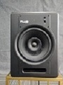 |
| 03 | Noise Monitoring | Precision Sound Level Meter | 1357 | TES | Measures sound pressure at the microphone |  |
| 04 | Noise Source | Speaker/TV | Recommended: FX8 Monitor Speaker | Fluid Audio | Plays noise and simulates external interference |  |
| 05 | Audio Collection | High-Fidelity Recorder | R44 | Roland | Records audio | 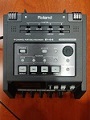 |
Arrangement Of Test Equipment And Instruments
Artificial Mouth
Model: 4227-A
Performance Specifications:
- Rated Output SPL:
- 200Hz - 2kHz: 110dB
- 100Hz - 8kHz: 100dB
- Distortion (@94dB):
- 200Hz - 250Hz: <2%
- above 250Hz: <1%
- Impedance: 4Ω
- Maximum Power: 10W
- Peak Power: 50W
- Mouth Diameter: 20mm
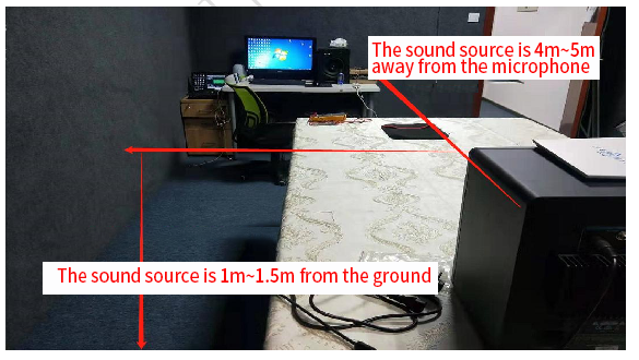
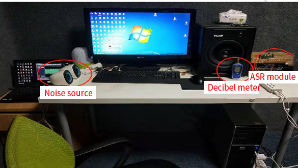
The artificial mouth is used to play the sound source. It should be positioned directly in front of the voice module’s microphone, with a horizontal distance of 4-5 meters. The sound source should be 1-1.5 meters above the ground (simulating normal human voice height), as shown in Figure 1.
Noise Source (Monitor Speaker)
Model: Fluid Audio FX8
Performance Specifications:
- Frequency Response: 35Hz - 22kHz (±3dB)
- Crossover Frequency: 2.4kHz
- LF Amplifier Power: 80W
- HF Amplifier Power: 50W
- Signal-to-Noise Ratio: >100dB (A-weighted)
- Polarity: Positive signal/input produces outward low-frequency displacement
- Input Impedance: 20kΩ (balanced), 10kΩ (unbalanced)
- Input Sensitivity: At max volume (102dB SPL), 85mV pink noise input yields 95dBA SPL output
- Power: 115V~50/60Hz or 230V~50/60Hz (user-selectable)
- Protections: RF interference, output current limiting, over-temperature, transient on/off, subwoofer filter, external fuse
- Enclosure: MDF with ethylene base
- Dimensions (single speaker): 340mm (H) × 254mm (W) × 270mm (D)
- Weight (single speaker): 9.8kg
If a monitor speaker is unavailable, a TV may be used as a substitute.
The voice module and precision sound level meter should be positioned on the same plane, 1 meter above the ground. The distance from the voice module’s microphone to the noise source should be at least 1.5 meters but not exceed 2 meters, as shown in Figure 2.
Precision Sound Level Meter
Model: TES 1357
Performance Specifications:
- Resolution: 0.1dB
- Measurement Range: 30–130dB
- Optional Spectrum Analysis Software: 1/1, ⅓, ⅙, 1/12, 1/24 octave
- Accuracy: ±1.5dB (ref 94dB @ 1kHz)
- A-Weighted Range: 30–130dB
- C-Weighted Range: 35–130dB
- Measurement Ranges: 30–80dB, 50–100dB, 60–110dB, 80–130dB
- Frequency Response: 31.5Hz–8kHz
- Display: 4-digit LCD, 0.1dB resolution, updated every 0.5s
- AC/DC Output: 2Vrms/full scale, 10mV/dB
The sound level meter should be placed as close as possible (≤5cm) to the voice module’s microphone, but must not touch it, as shown in Figure 2.
Computer and Device Under Test
The computer and the device under test are connected via a USB-to-UART converter, allowing the computer to receive serial information from the module. The spatial relationship among the computer, module, sound level meter, and noise source is shown in Figure 2.
After arranging various instruments and equipment and modules to be tested, we can use the automated speech recognition testing tool provided by our company to test.
Automated Recognition Test Tool
Version: v8.1.1
1. Interface and Directory
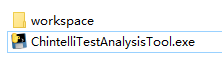
1.1 Tool Directory
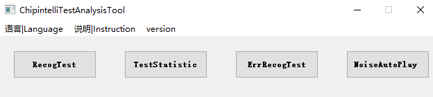
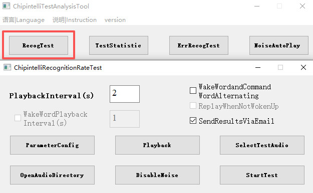
1.2 Tool Interface
The tool supports both Chinese and English interfaces. Click “语言|Language” to select your preferred interface.
2. Automated Recognition Test Tool
2.1 Structure Specification
2.1.1 Workspace
.\workspace\auto_rectest_tool
2.1.2 Directory Structure
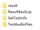
result/: Test Result directoryResultBackUp/: Result backup directorySetTestInfo/: Test information config directoryTestAudioFiles/: Test audio directory
2.1.3 Tool Interface
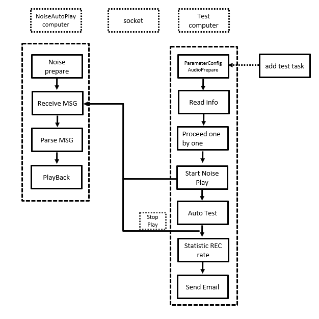
2.1.4 Principles of Automated Test
2.2 Test Audio Preparation
2.2.1 Audio Preprocess
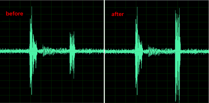
2.2.1.1 Audio Normalization
When the volume levels of recorded test audio files are inconsistent, audio normalization must be performed before testing.
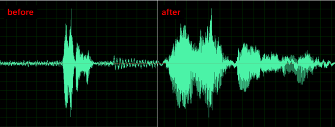
2.2.1.2 Remove Silence
To speed up testing and reduce unnecessary time waste, trim silence at the beginning and end of each audio clip.
2.2.2 Audio Storage
2.2.2.1 Directory Storage Format
There are two ways to organize audio files:
-
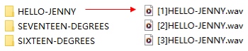
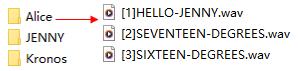
Same Content, Different Speakers: Audio files with the same content but different speakers in the same directory.
-
Same Speaker, Different Content: Audio files from the same speaker with different content in the same directory.
2.2.2.2 Audio File Format
- Format:
.wav - Sample rate: 44.1 kHz
- Channels: Mono
- Naming convention:
[number]CommandWord.wav
Examples:
- [1]HELLO-JENNY.wav
- [2]SIXTEEN-DEGREES.wav
Note: - The number determines playback order (ascending) - Command words in filenames must exactly match those in the language model - The tool compares command words from filenames with recognition results to determine accuracy
2.3 Test Steps
2.3.1 Automatic Playback Noise Environment Setup
Skip this section if automatic playback with background noise is not required.
2.3.1.1 Set Up Noise Test Local Area Network
Purpose: Enable automatic background noise playback during testing.
Requirements: - Connect test logging computer and noise playback computer in the same LAN - Noise playback computer = “server” - Test logging computer = “client” - Use Ethernet cables (not Wi-Fi) for stability - Based on Windows 10 configuration
Configuration Steps:
-
Hardware Networking - Connect computers directly using an Ethernet cable
-
Configure Server IP Address - Right-click network icon in system tray - Select “Open Network & Internet settings” - Navigate to: Ethernet → Network and Sharing Center → Change adapter settings - Right-click Local Area Connection → Enable → Properties - Double-click “Internet Protocol Version 4 (TCP/IPv4)” - Enter IP settings - Click OK to apply
-
Configure Client IP Address - Set test logging computer IP to 192.168.191.121
-
Disable Firewall - Open Start Menu → Settings → Update & Security - Select Windows Security → Firewall & network protection - Turn off all firewall profiles (Domain, Private, and Public networks)
2.3.1.2 Prepare Noise Automatic Playback Software
-
Installation - Copy the tool to the noise playback computer
-
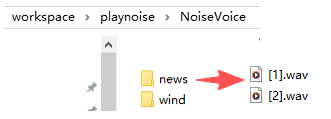
Prepare Noise Audio Files - Place noise files under
NoiseVoice/directory - Create subdirectories for each noise type (e.g.,NoiseVoice/RangeHood/,NoiseVoice/News/) - Name files as[1].wav,[2].wav, etc. - Format: 44.1 kHz, mono channel
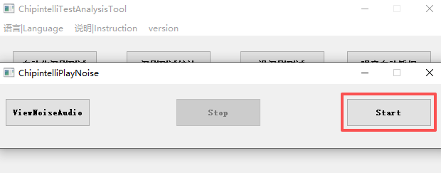
- Start Noise Playback
- Click “Start” button to begin automatic noise playback
2.3.2 Test Firmware Development and Flashing
2.3.2.1 Firmware Build Requirements
- Disable all print logs unrelated to recognition output during firmware development
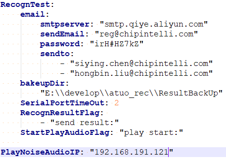
2.3.2.2 Printing Requirements
- Format:
send result:HELLO-JENNY 120 send result:: Recognition result flag (configurable in.\workspace\config\config.ymlunder “RecognResultFlag”)HELLO-JENNY: Recognition result120: Confidence score