Instructions for Offline Upgrade Tool
-
This document is the instruction manual for our offline upgrade tool. The offline upgrade tool is our self-made module board, onboard SD card, speaker, key, power switch and other hardware. Just connect the upgraded board to the offline upgrade tool, and you can update firmware for other module boards without computers and power supply. If the user wants to obtain the upgrade dog tool, please click batch purchase Purchase or contact our business personnel.
-
The main function of this tool is to copy the configuration file into the SD card, insert the SD card into the offline upgrade tool card slot, connect the upgraded board UART0 to the offline upgrade tool interface, power the offline upgrade tool, and operate the offline upgrade tool button according to the prompt tone broadcast by the speaker to update the firmware of the upgraded board.
-
The difference between the offline upgrade tool and the serial port upgrade tool is that the offline upgrade tool has no graphical interface, but the user can hear the prompt tone, and does not need a computer. As long as it is powered by a USB power pack, it can work, and it is convenient to carry and move, and can be used anywhere.
-
The following is a detailed description of how to handle the common problems in the SD card data upgrade example of the environment setup and upgrade process.
1. Environment construction
1.1. Upgrading equipment
- The following table describes the number of hardware names required for offline upgrade tools and how to obtain them.
| Name | Quantity | Description |
|---|---|---|
| Offline upgrade of motherboard | 1 | Provided by Chipintelli (Chipintelli provides corresponding materials) |
| DuPont Line | Several | Provided by/purchased by Chipintelli |
| SD card | 1 | Provided by/purchased by Chipintelli |
| SD card reader | 1 | Provided by/purchased by Chipintelli |
| USB serial port tool | 1 | Provided by/purchased by Chipintelli for offline upgrade |
| Horn | 1 | Provided by/purchased by Chipintelli |
| TYPE-C power cord | 1 | Provided by/purchased by Chipintelli |
| The board to be upgraded | / | The board to be upgraded is currently applicable to the CI110X/CI1122/CI130X scheme |
1.2. Upgrade Framework
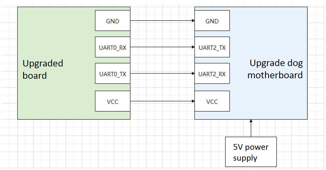
- The following figure shows the connection diagram between the offline upgrade tool and the upgraded board, identifying the detailed correspondence between the serial port number pins and the power supply requirements.
1.3. Upgrade Environment
- The structure of the offline upgrade software package is shown in the figure below. Users will receive the software package when they obtain the upgrade dog tool.
-
Burn the firmware of the offline upgrade motherboard: use the serial port upgrade tool provided by Chipintelli (please refer to the Instructions for Serial Port Upgrade Tool) to upgrade the firmware of the offline upgrade motherboard, and use the card reader to copy the information required for the upgrade to the empty SD card. Before powering on the board, put the SD card into the card slot.
-
The following table describes each folder file in detail.
| Name | Description |
|---|---|
| sdcard_ Ci110x | Information required for upgrading ci110x series chip modules |
| sdcard_ Ci112x | Information required for upgrading of ci112x series chip modules |
| sdcard_ ci110x_ Materials required for lite | ci110x series chip (4M Flash) module upgrade |
| sdcard_ Ci130x | Information required for upgrading the ci130x series chip module |
| OfflineProgramTool_ VXXX. Bin | Offline upgrade of motherboard firmware, burning to offline upgrade of motherboard |
| version. Md | Version release record |
| OfflineProgramTool User Manual Pdf | Instructions |
- When upgrading the ci110x module, the sdcard_ All files in the ci110x directory are copied to the empty SD card through the SD card reader. When upgrading the ci112x module, use the sdcard_ The files in the ci112x directory. When upgrading the ci110x (4M Flash) module, use the sdcard_ ci110x_ Files in lite directory. When upgrading the ci130x module, use the sdcard_ The files in the ci130x directory (There are 4 items in total. Don’t put other irrelevant files in the SD card.) .
1.4. Description of offline upgrade hardware
Note
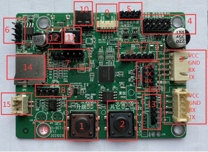
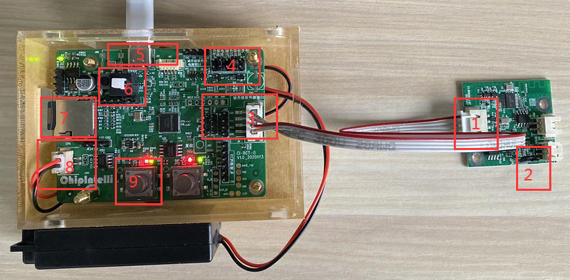
The interface sequence of the three groups of upgraded boards at No. 3 is: the left two groups of black pins are VCC, TX2, RX2 and GND from top to bottom, and the right white seat is VCC, GND, RX2 and TX2 from top to bottom.
- The number description in the following table corresponds to the numerical designated area in the figure above
| No. | Name | Description |
|---|---|---|
| 1 | Upgrade button | Start upgrading |
| 2 | Other keys | Start comparing partition information. After the upgrade is completed, press this button to compare the partition information. Read the firmware partition information of the upgraded board, compare it with the firmware partition information stored in the SD card, and check the correctness of the burning (The green light indicates that the comparison is passed. The red light indicates that the comparison is failed.) |
| 3 | Offline upgrade mainboard UART2 (upgrade interface) | There are three groups of interfaces with different specifications, sizes and functions that can be selected to connect the UART0 of the upgraded board and supply power to the upgraded board Note: RX2 is connected to the upgrade board TX0, and TX2 is connected to the upgrade board RX0 |
| 4 | Level selection of the upgraded board | Serial port level and power supply level jumper selection of the upgraded board. There are two serial port levels (3.3V5V). There are three power supply levels (3.3V5V others) |
| 5 | External power interface of the upgraded board | When the upgraded board has a power supply demand of more than 5V and less than or equal to 12V, external power can be connected here, and the power supply level jumper of the upgraded board can be selected (Others) |
| 6 | Lithium battery interface | 3.7V lithium battery interface (reserved) |
| 7 | Offline upgrade mainboard UART0 | Offline upgrade mainboard chip program download interface** Define from left to right (5V, RX0, TX0, GND, PG_EN, 3.3V) |
| 8 | Offline upgrade mainboard power supply interface 1 | Offline upgrade mainboard power supply interface 1 (reserved) |
| 9 | MIC interface | MIC interface (reserved) |
| 10 | Offline upgrade of mainboard power supply interface 2 | Offline upgrade of mainboard power supply interface 2, TYPE-C cable (5V), which can be connected to the power bank for power supply, and plugged in the TYPE-C cable for power supply** The yellow indicator above No. 6 flashes, indicating that the battery is charging, and the constant light indicates that the battery is fully charged |
| 11 | Offline upgrade mainboard power switch | The mainboard can only be powered on. Press this switch to turn off the power, and pop it to turn on the power. Be careful to turn off the power when not in use to avoid battery power consumption |
| 12 | Battery power supply button | Press the power supply switch. If the yellow indicator above No. 6 is not lit, you need to press this button to activate the battery |
| 13 | Reserved | * * (Reserved) |
| 14 | SD card slot | SD card slot (Do not plug or unplug the SD card with power) |
| 15 | Offline upgrade motherboard speaker interface | Plug in the speaker, and the offline upgrade motherboard will have a prompt tone to help upgrade after it is powered on |
| 16 | Version information | Note that the main difference between V1.0 and V1.1 is that the definitions at 3 are different |
| 17 | IIS interface | Digital audio interface (reserved) |
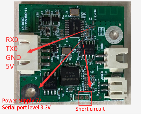
1.5. Example of upgraded board appearance
2. Upgrade process
Note
If the upgraded board is removed during the upgrade process, the upgrade cannot be restarted until the upgrade is completed.
Power on announcement : Welcome to use the Chipintelli upgrade tool, please wait for self inspection. Self check successfully announced : self check is completed, please connect the upgraded board and press the upgrade button. Self test failure broadcast : memory card is abnormal, please power on again after power off and check. Press the upgrade button to broadcast : upgrading, please wait. Upgrade successful broadcast : Upgrade successful. Upgrade Failure Advertisement : Upgrade failed, please check the document to confirm the reason.
3. SD card information
3.1. SD Card Root Directory
- Preview of SD card data (SD card root directory) CI110X series, CI112X series, CI110X (4M flash) series and CI130X series root directory. The figure below shows ci110x and ci110x from left to right_ The contents of lite, ci112x, and ci130xsd root directories.
| Root directory | Subdirectory | Subdirectory | Subdirectory |
|---|---|---|---|
| config | batch_ production_ config. Ini | - | Basic upgrade configuration |
| Log | - | - | Upgrade log storage directory |
- ci1xxx_ general. Bin file : the client firmware to be burned. The file name must be consistent with the configuration file, and the length is limited to 255 bytes.
- ci1xxx_ Updater.bin file : Assists MASKROM to burn customer firmware.
3.2. Configuration Resolution
Basic upgrade configuration: batch under SD card config directory_ production_ Config.ini file.
Notes
The file consists of a key and a value pair. [XXX] represents a key, and the next line is the value of the key.
Note
- It is prohibited to fill unnecessary items in all configuration files.
- The key cannot be deleted or modified. Note that the two values that do not need to be modified cannot be modified. Other values can be modified by referring to the comments or the following detailed examples.
3.2.1. Example 1 - Replacement Firmware
Step 1 : Assume that the configuration filled in by the serial port upgrade packaging tool (PACK_UPDATE_TOOL. exe) is as follows.
(1) The software name is Firmware.
(2) The software version is 2.0.0.
(3) The generated firmware name is: Firmware_ V200.bin.
Step 2 : Firmware to be burned_ V200.bin is placed in the root directory of the SD card.
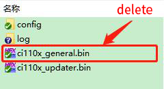
(1) Delete ci11xx under SD card root directory_ general.bin.
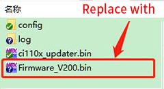
(2) And replace it with the firmware to be burned generated by packaging in step 1_ V200.bin.
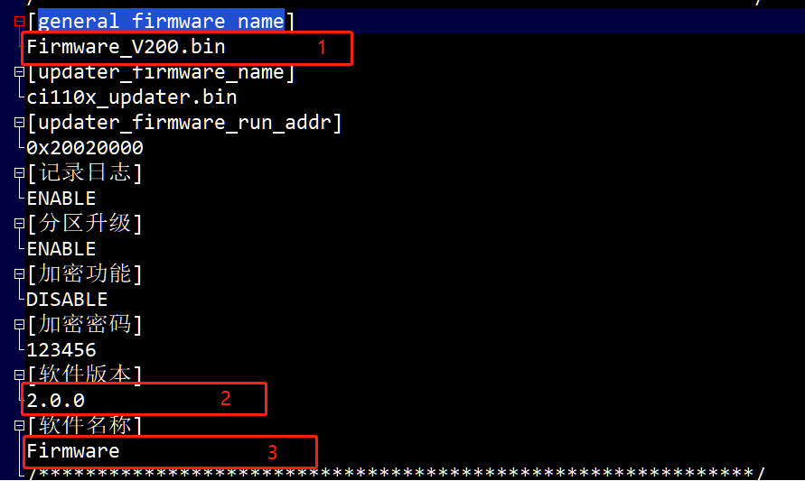
Step 3 : batch under SD card config directory_ production_ The config.ini file is modified to.
(1) Modify the value of [general_firmware_name] to Firmware_ V200.bin.
(2) Modify the value of [Software Version] to 2.0.0.
(3) Modify the value of [Software Name] to Firmware.
Note
Software name The software version must be generated by the packaging tool. The value of the [general_firmware_name] item can be renamed. Rename method. See 3.2.2 Example 2 for details.
3.2.2. Example 2 - Replacing Rename Firmware
Step 1 : Assume that the configuration filled in by the serial port upgrade packaging tool (PACK_UPDATE_TOOL. exe) is as follows.
(1) The software name is Firmware.
(2) The software version is 2.0.0.
(3) The generated firmware name is: Firmware_ V200.bin.
Step 2 : Generate Firmware from Step 1_ Select the V200. bin file and right-click to rename it as Smart Housekeeper_ V200.bin**.
Step 3 : Rename the Smart Housekeeper_ V200. bin Put it in the root directory of SD card and delete ci11xx_ general.bin**.
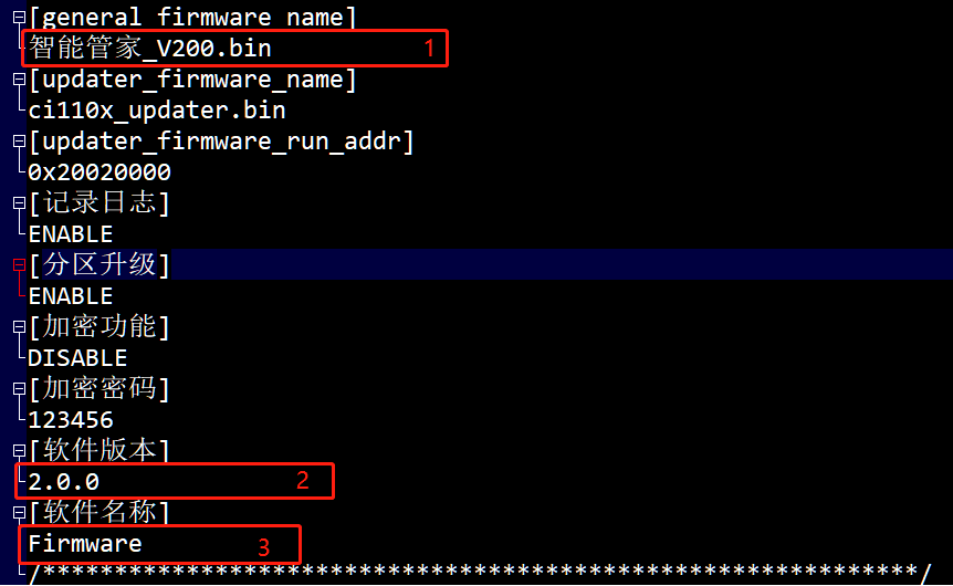
Step 4 : batch under SD card config directory_ production_ The config.ini file is modified to.
Note
- As shown in the figure above, the software name of the software version is still filled in by the packaging tool (PACK_UPDATE_TOOL. exe), while the firmware name is renamed.
- Renaming does not change the software version and name. It is fixed when packaged by the packaging tool. It is recommended to directly use the firmware name generated by (PACK_UPDATE_TOOL. exe) (example 1 in section 3.2.1) . If you use the renaming method (example 2 in section 3.2.2), you must record the software version and software name filled in during packaging to ensure correct configuration.
3.2.3. Example 3 - Log Switch
(1) Change the value of [Log] to DISABLE: the offline upgrade log file will not be generated in the SD card log directory.
(2) Change the value of [Log] to ENABLE: an offline upgrade log file will be generated in the SD card log directory. If you are interested, you can open it to view the content. The size is limited. After a long time of heavy use, it needs to be cleaned regularly. Delete and move all the files in the log directory.
4. Upgrade Example
4.1. Assumption 1
4.1.1. Conditions
(1) The required level of the serial port of the upgraded board is 3.3V, and the power supply level is 5V.
(2) Firmware name: Firmware_ Intelligent butler_ V200.bin.
(3) Software name (the software name filled in when packaging firmware): Firmware.
(4) Software version (the software version filled in when packaging firmware): 2.0.0.
Note
Package to generate firmware named Firmware_ V200.bin, condition (2) is renamed.
4.1.2. Modifying SD Card Configuration File
(1) Modify config batch according to the condition 234 in section 4.1.1_ production_ The config.ini configuration file is shown below.
(2) Replace the firmware to be upgraded.
(3) Put the SD card into the offline upgrade motherboard card slot.
4.1.3. Hardware connection
- The number description in the following table corresponds to the numerical designated area in the figure above.
| No. | Description |
|---|---|
| 1 | The upgraded board UART0 is connected to the UART2 of the offline upgraded motherboard |
| 2 | Upgrade board PG_ The EN jumper is shorted to 3.3V |
| 3 | Upgrade the mainboard UART2 offline and connect it to the upgraded board UART0 |
| 4 | Select the upgrade level and the power supply voltage of the upgraded board. According to the condition 1 in section 4.1.1, select 3.3V for the upgrade level jumper and 5V for the power supply voltage jumper of the upgraded board |
| 5 | Offline upgrade power supply interface (connected to 5V power supply or computer USB or mobile phone charger interface) |
| 6 | Power switch (press to turn off the power first) |
| 7 | SD card (the firmware to be upgraded has been copied into it) |
| 8 | Horn interface |
| 9 | After the system self check is OK, press the Upgrade button to start the upgrade |
4.1.4. Upgrade steps
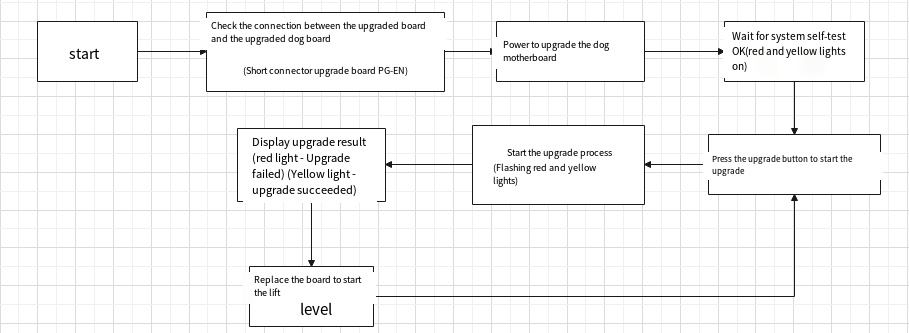
(1) Select the power supply interface according to Section 1.4 to supply power for offline upgrade, and you will hear the audio of “Please wait while self checking”.
Note
It is considered here that the control program has been downloaded for offline upgrade of motherboard chip, otherwise it is necessary to download the program for offline upgrade of motherboard before using it.
(2) Wait for the system self-test to be OK, and then proceed to the next step after hearing “After the self-test is completed”. The red and yellow lights above the upgrade button are on; If you hear other audio, please refer to Section 5.1 for troubleshooting.
(3) Press the upgrade button, hear the audio of “upgrading, please wait”, and the red and yellow lights flash, indicating that the upgrade is in progress.
(4) Wait until the upgrade is completed. If the yellow light is on and the red light is off, hearing “Upgrade succeeded” means that the upgrade has been completed; If the red light is on and the yellow light is off, the upgrade fails. If you hear other audio, please refer to Section 5.1 for troubleshooting.
4.2. Assumption 2
4.2.1. Conditions
The required level of the serial port of the upgraded board is 5V, and the power supply level is 5V.
4.2.2. Steps
According to the conditions, 5V is selected for the jumper of the upgrade level (the level required by the serial port of the upgraded board), and 5V is selected for the jumper of the power supply voltage of the upgraded board. For others, refer to Section 4.1.
4.3. Assumption 3
4.3.1. Conditions
The required level of the serial port of the upgraded board is 5V, and the power supply level is greater than 5V and less than or equal to 12V.
4.3.2. Steps
According to the conditions, select 5V as the jumper for the upgrade level (the level required by the serial port of the upgraded board), and select (others) as the jumper for the power supply voltage of the upgraded board. For others, refer to Section 4.1. Refer to the external power supply at No. 5 in Section 1.4.
4.4. Assumption 4
4.4.1. Conditions
The required level of the serial port of the upgraded board is 5V, and the power supply voltage is greater than 12V, or it is not convenient to use offline to upgrade the above power supply.
4.4.2. Procedure
According to the conditions, select 5V as the jumper for the upgrade level (the level required by the serial port of the upgraded board), remove the cap of the jumper for the power supply voltage of the upgraded board, and use the power supply of the upgraded board (keep the power off state first). For others, refer to Section 4.1. When you hear the announcement of “Upgrading, please wait”, power on the upgraded board manually.
5. Common problem handling
Some problems and troubleshooting methods are described in detail below.
5.1. The power indicator is not on
Check whether the offline upgrade is connected to the power supply and whether the power supply is normal 5V power supply.
5.2. No announcement after pressing the power button
(1) If the power indicator is on, check whether the power supply is normal 5V.
(2) Whether the power button is in the pop-up state. After 2 seconds (other keys), the upper indicator lights up, indicating that the button is in normal state.
(3) If the indicator above the upgrade button lights up after 20 seconds, please confirm whether the horn is connected.
5.3. Hearing the audio of “self test failure”
(1) Re energize the offline upgrade.
(2) Confirm whether the SD card is inserted before power on and whether it is completely inserted into the SD card slot.
(3) Confirm that the contents of the SD card are files provided for technicians, and whether there are any missing files, files copied into the wrong configuration.
(4) Replace an SD card and power it on again.
5.4. Hear the “Upgrade Failed” audio
(1) Confirm whether the offline upgrade motherboard and the upgraded board are connected normally.
(2) Re energize the offline upgrade.
(3) Confirm whether the firmware in the SD card is the firmware of the upgraded board.
(4) Confirm that the RX0 of the upgraded board is connected to the offline upgraded TX2, and the TX0 is connected to the offline upgraded RX2.
(5) Confirm whether the two jumpers of the upgrade level of the offline upgrade motherboard and the power supply voltage of the upgraded board are correct.
(6) Confirm the upgraded board PG_ Whether the EN is short circuited 3.3V.
