CI-D0XGS02S Module Datasheet
Module Introduction
Overview
This module is a general-purpose, portable, low-power, high-performance voice recognition module designed for cost-effective offline voice applications. The model CI-D0XGS02S is available in three variants: - CI-D01GS02S: Features CI1301 main chip - CI-D02GS02S: Features CI1302 main chip - CI-D03GS02S: Features CI1303 main chip
All three models maintain full pin compatibility, with the CI1303 chip in the CI-D03GS02S offering increased Flash memory capacity compared to CI1302 and CI1301, enabling support for more command terms, larger algorithm models, and enhanced software functionality.
Key Features
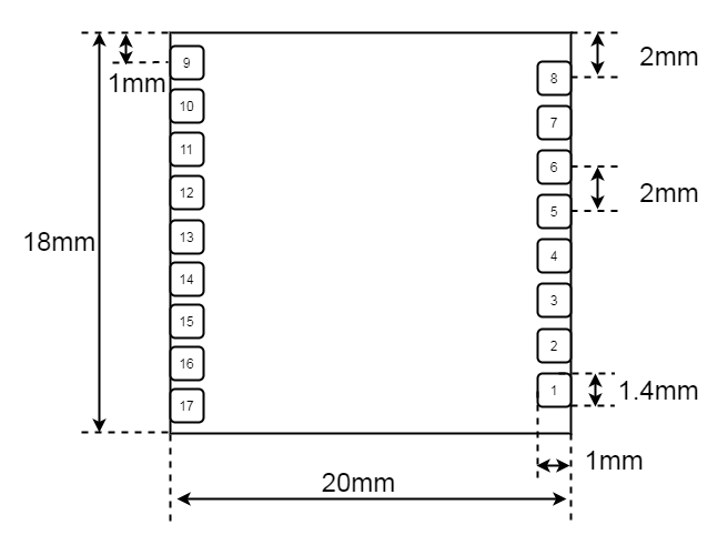
- Compact Design: 18mm × 20mm
- Wide Voltage Range: 3.6V to 5V
- Audio Interfaces: Single microphone input and speaker output
- Communication: Dual UART interfaces
- Control: Two PWM interfaces
- Packaging: Dual-row castellated holes and through-hole pins for flexible SMT or through-hole mounting
Advanced Capabilities
- Neural Network Processing: Onboard neural network processor for offline voice recognition
- Audio Enhancement:
- Single-microphone noise reduction
- Acoustic echo cancellation
- 360° omnidirectional audio pickup
- Environmental noise suppression
- Performance:
- 97%+ recognition accuracy
- Response time as low as 0.2 seconds at 10 meters
- No network dependency for operation
- Reliability: Industrial-grade components for robust performance
- Power Efficiency: Suitable for battery-powered applications
Development Options
The module is compatible with the following development solutions:
-
Development Backplane - Use with the CI-B02-MB development backplane - CI-B02-MB Evaluation Kit Documentation
-
Integrated Development Board - All-in-one solution with built-in main chip - No separate module required - CI-D06GT01D Development Board Documentation
Module Selection Guide
| Module Variant | Up to 100 Commands | Up to 200 Commands | Up to 500 Commands |
|---|---|---|---|
| Single-Mic Offline Voice Module | CI-D01GS02S | CI-D02GS02S | CI-D03GS02S |
Main Chip Specifications
CI1301/CI1302/CI1303 AI Voice Processor
Key Features
- Neural Network Acceleration: Dedicated BNPU V3 processor
- CPU Core: High-performance processor core
- Clock Speed: Up to 220MHz
- Memory: 640KB SRAM
- Power Management: Integrated PMU and RC oscillator
- Audio Processing: Dual-channel high-performance, low-power Audio Codec
Peripheral Interfaces
- Communication:
- Multiple UART interfaces
- IIC interface
- IIS interface
- Control:
- PWM outputs
- General-purpose I/Os (GPIO)
- PDM interface for digital microphones
- System:
- Flexible boot options
- Low-power modes
Design Advantages
- Minimal External Components: Requires only basic passive components
- Cost-Effective: High level of integration reduces BOM cost
- Versatile: Supports various hardware configurations
For comprehensive technical details, refer to the CI1301/CI1302/CI1303 Chip Datasheet.
Application Scenarios
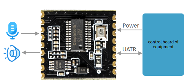
Integration Options
-
Voice Recognition Module - Connect to existing main control board - Uses UART for command/status communication
-
Standalone Controller - Direct peripheral control - Built-in command processing - Customizable firmware
Power Requirements
- Input Voltage: 5V DC
- Current: 500mA recommended
- Regulation: Stable power supply required (<30mV ripple)
Audio Configuration
- Microphone: External electret microphone
- Speaker: 4Ω or 8Ω speaker
- Audio Processing:
- Noise reduction
- Acoustic echo cancellation
- Beamforming (software configurable)
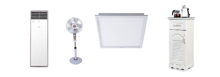
Supported Applications
The CI-D02GS02S module supports up to 150 offline voice commands, making it ideal for: - Smart home appliances (air conditioners, fans) - Consumer electronics (toys, lighting) - Industrial controls - Automotive accessories - Smart home devices
Module Specifications
Physical Layout
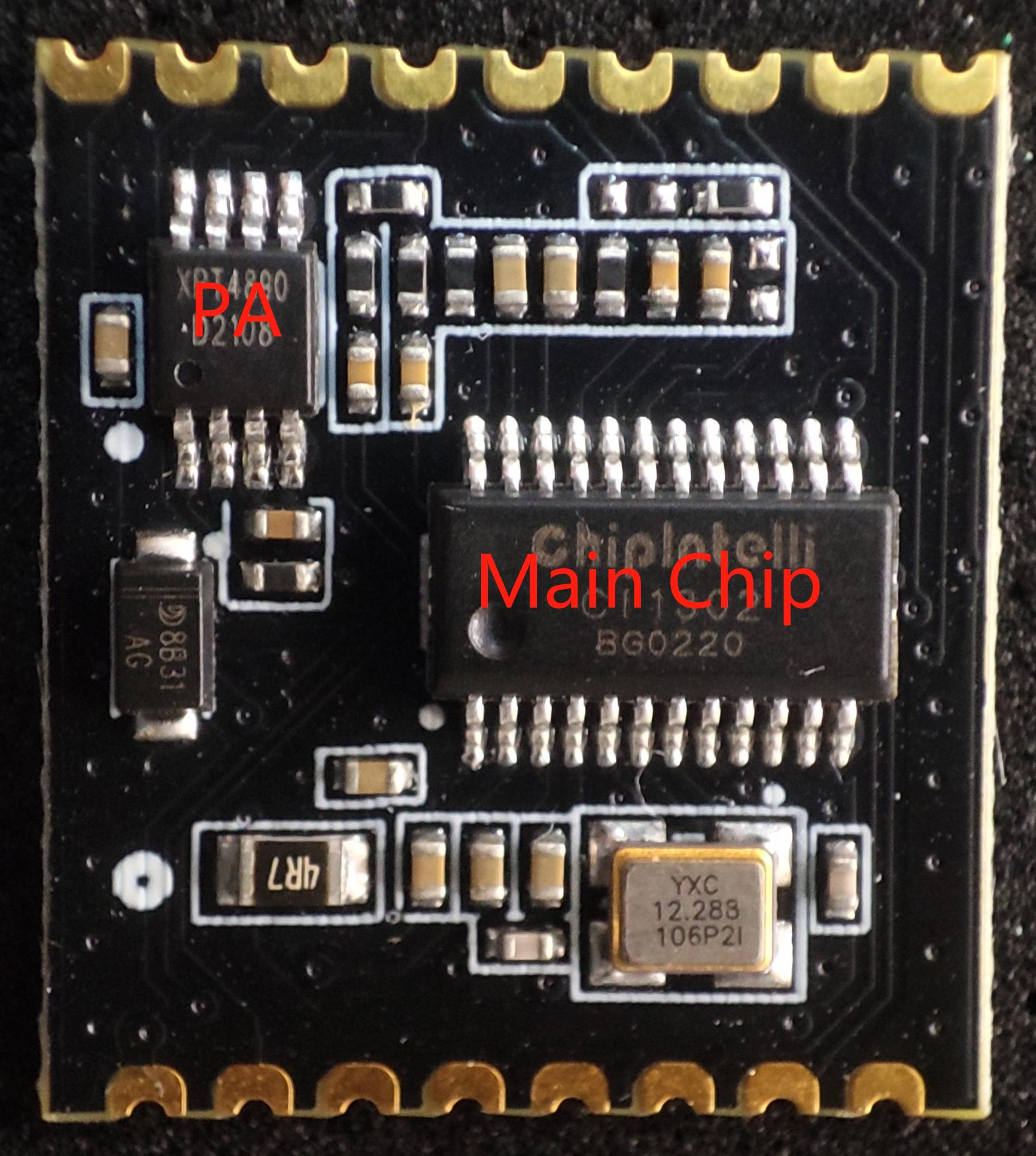

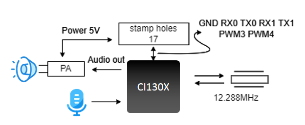
The module’s physical appearance is shown in Figure 4. The voice recognition module features single-sided surface mounting and primarily includes a voice recognition chip (CI1301/CI1302/CI1303) and an audio power amplifier. Voice commands are captured by the microphone and processed by the voice recognition IC for speech recognition and command interpretation. The processed feedback audio is then sent to the audio power amplifier, which drives the speaker with a maximum output power of 1.1W at 8Ω or 2W at 4Ω.
Note: The image is for reference only. The silkscreen markings on components may vary between production batches, but these variations will not affect the module’s performance. The actual product shall prevail.
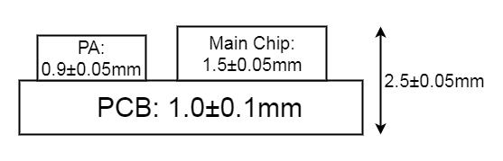
Module Dimensions
Pinout Diagram
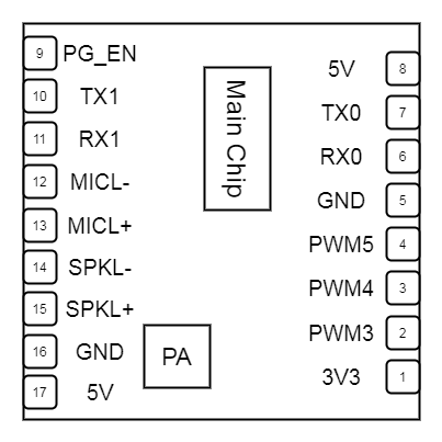
Pin Interfaces
-
Microphone Input - Differential input configuration - Recommended microphone specifications:
- Sensitivity: -32 ± 3dB
- SNR: ≥65dB
- Compatible Microphone List
-
Speaker Output - Bridge-tied load (BTL) configuration - Recommended speaker specifications:
- 4Ω or 8Ω impedance
- Enclosed or baffled design recommended
- Compatible Speaker List
-
UART Interfaces - UART0: Firmware Update (3.3V level)
- Add 100Ω series resistor in RX line
- For 5V compatibility: Add 10kΩ pull-up to 5V
- UART1: Main control communication
-
PWM Outputs - Configurable as GPIO or PWM - Can drive LEDs or control external devices
Pinout Table
| Pin | Name | Type | 5V Tolerant | Default State | Function |
|---|---|---|---|---|---|
| 1 | 3.3V | P | - | - | 3.3V Output (max 10mA) |
| 2 | PWM3 | IO | ✓ | IN, T+D | GPIO/IIS_SCLK/PDM_DAT/UART2_TX/PWM3 |
| 3 | PWM4 | IO | ✓ | IN, T+D | GPIO/IIS_MCLK/PDM_CLK/UART2_RX/PWM4 |
| 4 | PWM5 | IO | ✓ | IN, T+D | External crystal input (Note 2) |
| 5 | GND | P | - | - | Ground |
| 6 | RX0 | IO | ✓ | IN, T+U | GPIO_PB6/UART0_RX/I2C_SCL/PWM2 |
| 7 | TX0 | IO | ✓ | IN, T+U | GPIO_PB5/UART0_TX/I2C_SDA/PWM1 |
| 8 | 5V | P | - | - | 5V Power Input |
| 9 | PG_EN | IO | ✓ | IN, T+D | GPIO_PA4/IIS_SDO/PWM2 |
| 10 | TX1 | IO | ✓ | IN, T+D | GPIO_PA2/IIS_SDI/I2C_SDA/UART1_TX/PWM0 |
| 11 | RX1 | IO | ✓ | IN, T+D | GPIO_PA3/IIS_LRCLK/I2C_SCL/UART1_RX/PWM1 |
| 12 | MIC- | AI | - | - | Microphone Negative |
| 13 | MIC+ | AI | - | - | Microphone Positive |
| 14 | SPK- | AO | - | - | Speaker Negative |
| 15 | SPK+ | AO | - | - | Speaker Positive |
| 16 | GND | P | - | - | Ground |
| 17 | 5V | P | - | - | 5V Power Input |
Important Notes: 1. The 3.3V output (Pin 1) can source up to 10mA maximum. 2. Pin 4 is dedicated to external crystal input and cannot be used for other functions. 3. PG_EN (Pin 9) controls programming mode when held high during power-up.
Some symbols in the above table are described as follows:
| Symbol | Description |
|---|---|
| I | Input |
| O | Output |
| IO | Bidirectional |
| P | Power or Ground |
| T+D | Tri-state with pull-down |
| T+U | Tri-state with pull-up |
| OUT | Defaults to output mode on power-up |
| IN | Defaults to input mode on power-up |
Electrical Characteristics
| Parameter | Condition | Min | Typ | Max | Unit | Notes |
|---|---|---|---|---|---|---|
| Supply Voltage | - | 3.6 | 5.0 | 5.5 | V | Note 1 |
| Broadcast Current | 8Ω 2W Speaker | - | 70 | - | mA | Note 2 |
| Operating Current | - | - | 40 | - | mA | Note 3 |
| Quiescent Current | 5V Supply | - | 35 | - | mA | / |
| I/O Voltage | - | 3.0 | 3.3 | 5 | V | / |
NOTE1: 5V is the typical supply voltage. Voltages above 5.5V may damage the module.
NOTE2: The module can draw up to 250mA during audio playback. A power supply capable of 500mA is recommended.
NOTE3: Typical value is measured in mute state. Maximum value is measured during recognition and audio playback.
Recommended Operating Conditions
| Parameter | Minimum Value | Typical Value | Maximum Value | Unit | Remarks |
|---|---|---|---|---|---|
| Module working ambient temperature | - 40 | 25 | 85 | ° C | / |
| Module storage environment temperature | - 40 | 25 | 100 | ° C | / |
| Module storage humidity | 0% | / | 5% | RH | / |
Application Guidelines
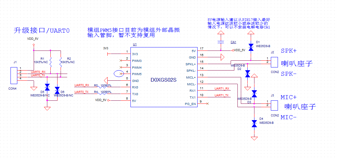
Backplane Design Reference
To use this module, a custom debug baseboard or host motherboard needs to be designed. The main function of the debug baseboard is to carry the module, supply power to it, provide sockets for the microphone and speaker, and support communication with the main controller.
-
It is recommended to place a large-value filter capacitor at the module’s power input to ensure stable 5V power supply. If the 5V input power has low ripple and minimal noise, the capacitor may be omitted.
-
To enhance electrostatic protection, add ESD components near the speaker and microphone sockets.
-
Reserve header pins for UART0 on the baseboard to facilitate future Firmware Updates.
-
The UART1 interface is used for communication with the main controller and can also be repurposed as general-purpose I/O (GPIO).
-
The two PWM interfaces can be used for lighting control.
A reference design is shown in the figure below.
Power On and Startup
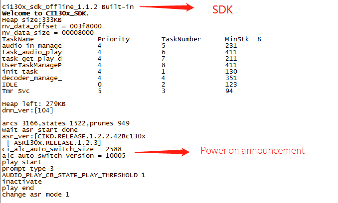
When using this module, mount it onto the baseboard or host motherboard and connect the speaker and microphone. Once the 5V power supply is connected, the module will automatically start. If the startup is successful, a power-on prompt sound will be played through the speaker. At the same time, UART debug messages will be output. Users can connect the UART port to a computer using a USB-to-UART debugging tool to view the printed messages in a serial debugging window. If the output shown matches the example in Figure 8, it indicates that the module has started normally.
Note that the module’s UART interface operates at a 3.3V high-speed logic level, but it also supports direct communication with 5V-level signals, eliminating the need for an external level shifter.
The module only requires an external 5V power supply to operate. Both Pin 8 and Pin 17 (recommended as the primary power input) are 5V input pins. The onboard power amplifier also uses a 5V supply. The 5V input should provide a stable current of at least 500mA, with voltage ripple no greater than 300mV.
Module Default Command Words
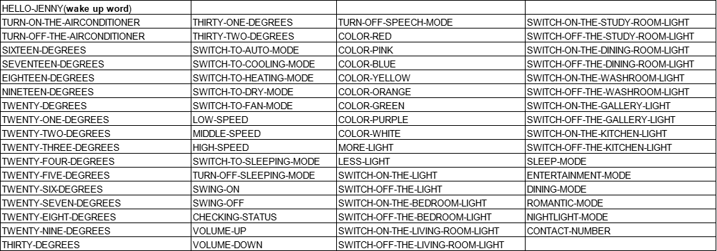
If it is a user’s mass production module, the firmware of the command term specified by the user will be flashed before leaving the factory. If not specified by the customer, the module will have its own default firmware with default command words for user testing, as shown in the following figure:
Module Default UART Protocol
The module for programming general firmware supports UART communication, which is used for communicating with the MCU or other system. The protocol of the UART port is extensible, and has the following characteristics:
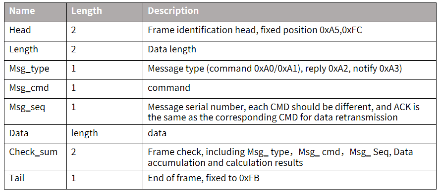
- Complete transmission package, including header and footer, length, verification, message type, and message serial number.
- Support variable length commands for easy expansion.
- Message type (command, notification, reply).
- Command message, configurable, reply to ACK. The notification message has no ACK.
- The message format will be the same as that of the bootloader upgrade, which is distinguished from the bootloader protocol through the header.
- The default baud rate is 9600.
- Note: Only UART0 interface is reserved for the module, and UART0 interface is the print output interface by default. If UART0 is required as the above UART protocol interface, the code must be modified, and the modification method can be implemented by referring to the UART protocol part of the documents in the ☞CI13XX chip SDK.
- Supported commands: query the protocol version number, query the system version number, set the volume (the volume rating is defined in user_config.h), play the local broadcast, reset commands, etc. The specific protocol format is shown in the following figure:
Example 1:
A5 FC 07 00 A0 91 18 01 55 E0 01 00 00 1B 9B 02 FB is resolved as follows:,
A5 FC:head
07 00: Valid data is 7byte
A0: This is the command word information
91: The command number is 0x91 (this data content is command word data)
18: Packet serial number, the 0x08th outgoing data of this UART, which is continuously accumulated
01 55 E0 01 00 00: semantic ID, UNIQUE
1B: Command word threshold
9B 02: Cumulative Sum
FB: End data
Note: If only command words and thresholds are concerned in the application, only 7 valid data in the blue part can be concerned.
Example 2:
A5 FC 02 00 A3 9A 17 00 B1 05 02 FB is resolved as follows:
A5 FC :head
02 00: Valid data 2byte
A3: currently notification data
9A: The command number is 0X9A (the data content this time is the voice module content change)
17: This UART sends data for the 0x07th time, and the value is continuously accumulated
00 B1: Valid data. (This data indicates entering the wake-up state)
05 02: Cumulative Sum
FB: End data
Note: This data is notification data, and the user can choose to use this information according to the situation.
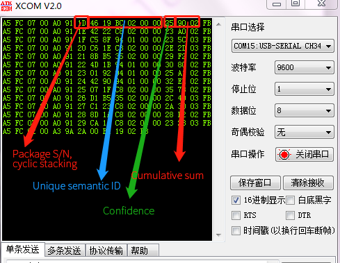
For more content analysis data, please refer to the UART protocol part in ☞CI130X chip SDK. The following figure is a reference screenshot of protocol data:
Software Development Guide
Custom Firmware Development
The CI-D0XGS02S module supports full firmware customization to meet specific application requirements. The development process is streamlined with our comprehensive SDK and development tools.
Development Process
-
SDK Setup - Download the latest CI130X SDK package - Install required toolchains and dependencies - Set up the development environment
-
Language Model Development - Create or customize language models - Develop acoustic models for specific use cases - Optimize wake word and command word recognition
-
Audio Customization - Record or generate custom voice prompts - Design audio feedback for user interactions - Implement audio effects and processing
-
System Integration - Configure UART communication protocol - Implement custom command handling - Integrate with external peripherals
-
Build and Package - Compile the firmware - Generate production-ready binary files - Create firmware update packages
Note: Refer to the CI130X SDK Documentation for detailed development guides, API references, and example code.
Firmware Flashing
Preparation before Flashing
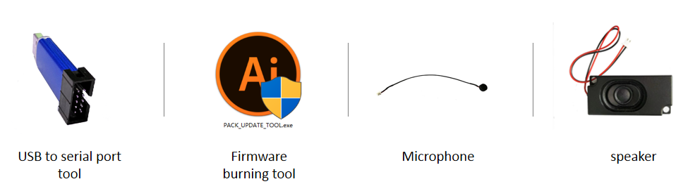
Before starting the firmware update process, ensure you have the following items ready:
- USB-to-serial programming tool and USB-to-serial programming tool driver
- Firmware flashing tool (pack_update_tool. exe)
- Firmware information (files in *. bin format)
- Microphone with 2.0mm pitch
- 2.5mm pitch speaker
- Several Dupont lines
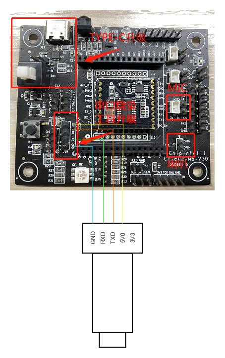
Hardware Connections and Flashing
As an example of the USB-to-serial programming tool shown in the above figure, the power, ground and UART transceiver pins of the USB-to-serial programming tool need to be connected with the corresponding pins of the module before flashing (note that the RXD and TXD of the USB-to-serial programming tool correspond to the UART0_TX and UART0_RX of the module respectively). The connection method is shown in the following figure.
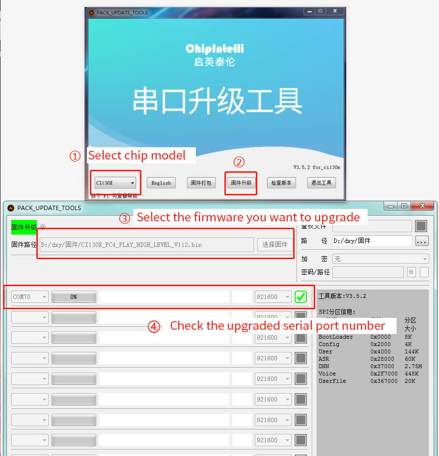
Open the firmware flashing tool (the tool can be found in the SDK development package under the CI130X_SDK\tools directory as PACK_UPDATE_TOOL.exe). Select the appropriate chip model based on the module you are using, then click the “Firmware Update” button. Choose the prepared firmware file and confirm the COM port number assigned by the computer to the USB-to-serial converter.
Once the module is powered on, it will enter Firmware Update mode and begin downloading the firmware. If the computer fails to recognize the USB-to-serial converter, please install the corresponding driver first. (The module should be upgraded while mounted on the baseboard.)
Function Test after Flashing
After the firmware is successfully flashed, it is recommended to perform a functional test on the module to verify whether the firmware is successfully flashed. During the function test, plug the microphone and speaker into the module to be tested, power on and observe whether it can be normally powered on and broadcast, and use the wake-up word and command word to test whether it can be normally wakened up and recognized. If it can work normally, the module functions normally and the flashing is successful; Otherwise, the flashing fails, and further investigation is required.
Troubleshooting
This chapter lists the problems that may be encountered in the use of some modules and the corresponding solutions.
The module cannot flash and update firmware.
After the above problems occur, please check the following operation points:
-
Check whether the UART pins are connected correctly, whether TX and RX are reversed, whether the USB-to-serial driver on the computer is functioning properly, and whether the correct COM port is selected in the flashing tool on the PC.
-
Also check whether there is a short circuit in the power supply that may have caused damage to the chip.
-
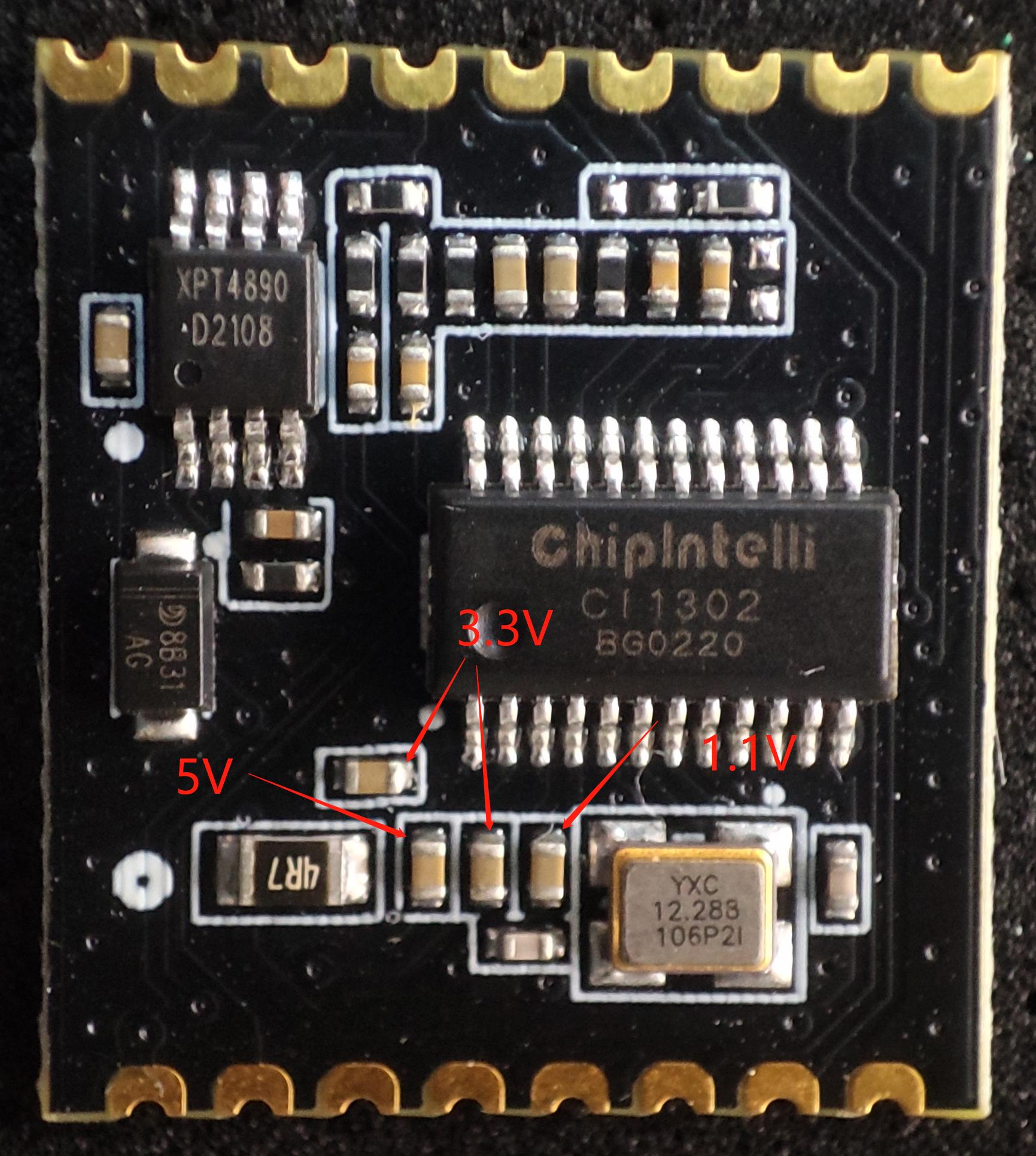
If all of the above checks are correct but the module still cannot be flashed, use a multimeter to measure the module’s supply voltages: 5V, 3.3V, and 1.1V. Refer to the measurement points shown in the diagram below.
-
If any abnormal voltage is found, it may indicate a hardware failure in the module. In that case, replace the module or perform hardware repair accordingly.
-
If all checks pass but the issue persists, please contact our technical support team for further assistance.
The module is flashed and there is no broadcast after power on.
After the above problems occur, please check the following operation points:
- Confirm whether the firmware matches the board;
- Confirm that the speaker is correctly connected and the power supply is normal;

After the module is flashed, the command word is announced but not recognized after power on:
- Check whether the connection between the microphone and the socket is intact;
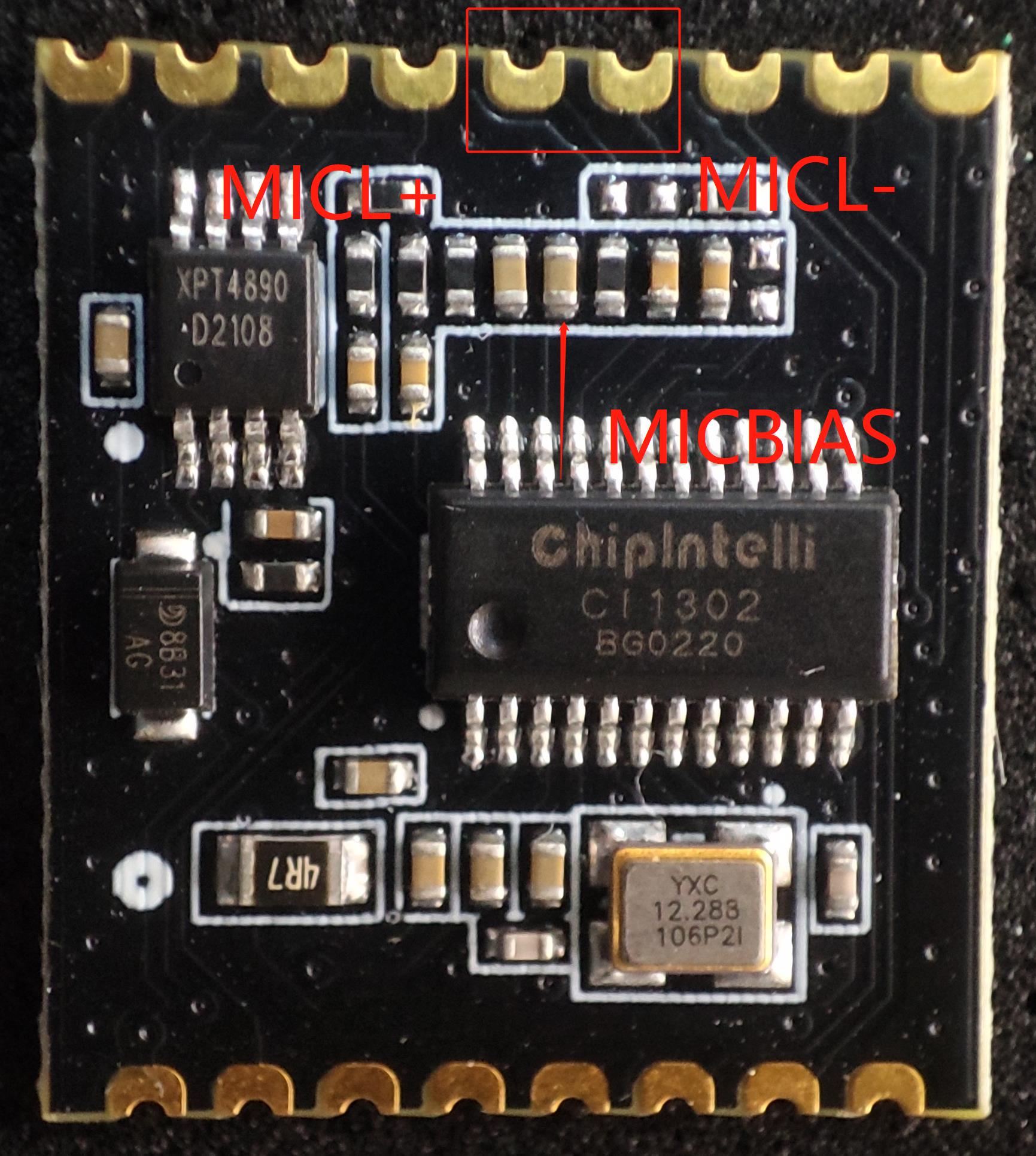
- Check whether the positive and negative pole directions of the microphone are consistent with the markings on the module board and are not inserted reversely;
- Use a multimeter to measure whether the MICBIAS pin corresponding to the main chip is about 2.8V, and use an oscilloscope to measure whether the microphone input pin has an input voice waveform (the voltage of each oscilloscope cell is adjusted to the 100mv gear). If the signal is normal, consider whether the firmware is correct, and if the signal is abnormal, observe whether the board hardware has physical damage. The measuring points are shown in the figure below. If there is no problem in the above inspection, please contact our technical support personnel for help.
Other Application Precautions
Since the CI1301, CI1302, and CI1303 chips have a high ESD rating and the module is designed for easy user expansion, no ESD protection components are integrated on the module itself. For products with strict ESD protection requirements, it is recommended to add ESD protection components on the baseboard, particularly near the microphone, speaker, and power connectors.
To ensure product reliability and quality, users are advised to wear anti-static wrist straps, gloves, or finger cots during inspection and soldering processes.
When using the module, make sure the microphone, speaker, power supply, and UART are connected correctly.
Users can debug their software using a USB-to-UART Debugging Tool. During debugging, serial print commands should be added at the appropriate locations in the SDK. After compilation and flashing the generated firmware, debugging and verification can be carried out.
All I/O pins on this module operate at typical 3.3V levels and support 5V-tolerant inputs.
When designing the baseboard or host motherboard, a capacitor of no less than 100μF should be placed at the module’s 5V power input. Microphone signal traces should be kept as short as possible and properly shielded. Speaker (SPK) traces should also be short and wide, and the routing area should be kept clear of any crossing signals.
The warpage of the control baseboard should not exceed 0.5% to prevent poor soldering of the module.
Module Production&Storage Guide, Ordering Information
Production and Storage Guide
-
Chipintelli stamp-hole packaged modules must be mounted using SMT (Surface Mount Technology) machines (except when using pin headers). After opening the package, the SMT mounting process must be completed within 24 hours; otherwise, the modules must be re-vacuum sealed before use.
-
The storage conditions for Chipintelli stamp-hole packaged modules are as follows: - The vacuum-sealed moisture-proof bag must be stored in a constant temperature and humidity environment at 25 ± 5 °C and 65% ± 10% RH. - A humidity indicator card is included inside the vacuum-sealed bag, as shown in the figure below:

- If the humidity indicator card shows any of the following color changes, the module must be baked according to the corresponding baking parameters:
- If the 30%, 40%, and 50% color rings on the humidity indicator card remain blue at the time of unpacking, bake the module continuously for 2 hours.
- If the 30% color ring turns pink at unpacking, bake the module continuously for 4 hours.
- If the 30% and 40% color rings turn pink at unpacking, bake the module continuously for 6 hours.
- If the 30%, 40%, and 50% color rings turn pink at unpacking, bake the module continuously for 12 hours.
- Baking parameters:
- Baking temperature: 125 ± 5°C
- Alarm temperature setting: 130°C
- After baking, allow the module to cool naturally to below 36°C before proceeding with SMT mounting.
- Number of drying cycles: 1 time
- If more than 12 hours elapse after baking without soldering, re-bake the modules.
-
If the unpacked time exceeds 3 months, SMT soldering of this batch of modules is prohibited because the PCB uses ENIG (Electroless Nickel Immersion Gold) finish. After 3 months, the pads oxidize severely, which may cause poor solder joints or missing solder during SMT assembly.
-
Before SMT assembly, perform ESD (Electrostatic Discharge) protection on the modules. Operators should wear anti-static gloves and wrist straps during the process.
-
To ensure a high pass rate for reflow soldering, all assembled products should undergo visual inspection and AOI (Automated Optical Inspection) to verify proper oven temperature control, correct component placement method, and accurate component orientation.
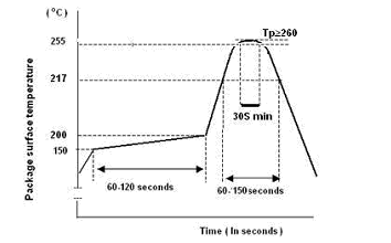
Recommended Reflow Profile
Ordering and Packaging Information
| Product model | Packaging method | Number of modules per pallet | Number of modules per package | Number of modules per box |
|---|---|---|---|---|
| CI-D01GS02S CI-D02GS02S CI-D03GS02S |
Tray+electrostatic bag+carton | 140pcs | 15 trays totaling 2100pcs | 3 bags totaling 6300pcs |
Procurement and technical support
If the user wants to purchase our product samples, please click on ☞Sample and Bulk Purchase to obtain more information.
If you want to obtain technical support, please log in to ☞Chipintelli AI Speech Development Platform.