Serial Port Programming Tool (PACK_UPDATE_TOOL.exe) User Manual
1. Overview
This document serves as the user manual for our company’s PACK_UPDATE_TOOL.exe UART programming tool. This tool is a software that is used to package binary code and data into a firmware, assisting firmware programming into the targeted chip/module through USB-to-UART Debugging Tool. The tool runs on Windows systems and displays a graphical interface on the computer. Users can click the corresponding icons to select the required functions. It supports two system languages, both Chinese and English for chip selection (CI110X series chips/CI112X series chips/CI13XX series chips), making it convenient to quickly package and generate firmware, and assist module board firmware programming in conjunction with USB serial port devices.
The following sections will introduce how to access tools, main functions, instructions on how to use, and common issues handling for UART protocol programmings.
2. Access to Tools
- Log in to ☞Chipintelli AI Speech Development Platform resource library to obtain the tool, named: UART programming Tool VXXX.rar.
- The tool is already included in the SDK package’s project directory, e.g.: CI11XX_SDK\tools\PACK_UPDATE_TOOL.exe.
- In the SDK package’s project directory: Double-click the (CI11XX_SDK\sample\internal\sample_xxx\firmware\Pack_Upgrade.bat) file to also open PACK_UPDATE_TOOL.exe.
3. Tool Features
3.1. Main Interface Functions
- Double-click to run PACK_UPDATE_TOOL.exe (the following uses V3.3.9 as an example) to see the main interface shown in the figure below.
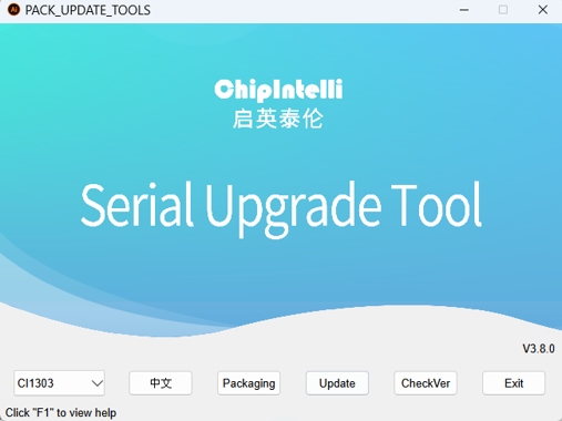
(1)Chip Selection: Select the chip category, including CI110X series chips, CI112X series chips, and CI13XX series chips.
(2)Interface Language Selection: Select the display language, either English or Chinese.
(3)Firmware Packaging: Click to enter the firmware packaging page.
(4)Firmware Update: Click to enter the firmware programming page.
(5)CheckVer: Click to check the version of the UART programming tool. The latest version can be updated when connected to the internet.
(6)Exit: Click to exit the tool.
(7)Press “F1” for Help: View more instructions about the UART programming tool offline.
3.2. Firmware Packaging Functions
- Click the (Firmware Packaging) button on the main interface to enter the firmware packaging page shown in the figure below.
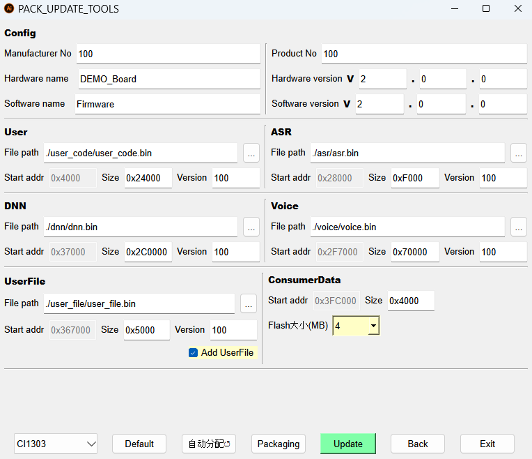
(1)Config (Firmware Basic Information Configuration)
- Manufacturer No: Fill in the corresponding number or keep the default.
- Product No: Fill in the corresponding number or keep the default.
- Hardware Name: Fill in Chinese/English or keep the default.
- Hardware Version: Modify to mark the version number or keep the default.
- Software Name: Fill in Chinese/English or keep the default.
- Software Version: Modify to mark the version number or keep the default.
Note
The firmware name generated by packaging consists of the software name and software version, for example, Firmware_V200.bin.
(2)User (User Code Storage Partition)
- File Path: ./user_code/user.bin. Or click the ellipsis icon on the right to select user.bin in the project directory (CI11XX_SDK\sample\internal\sample_xxx\firmware\user_code).
- Reserved Size: Increase or decrease in multiples of 0x1000, or keep the default.
- Current Version: Version number of user.bin, can keep the default.
(3)ASR (Language Model Storage Partition)
- File Path: ./asr/asr.bin. Or click the ellipsis icon on the right to select
asr.binin the project directory (CI11XX_SDK\sample\internal\sample_xxx\firmware\asr). - Reserved Size: Increase or decrease in multiples of 0x1000, or keep the default.
- Current Version: Version number of asr.bin, can keep the default.
(4)DNN (Acoustic Model Storage Partition)
- File Path: ./dnn/dnn.bin. Or click the ellipsis icon on the right to select
dnn.binin the project directory (CI11XX_SDK\sample\internal\sample_xxx\firmware\dnn). - Reserved Size: Increase or decrease in multiples of 0x1000, or keep the default.
- Current Version: Version number of dnn.bin, can keep the default.
(5)Voice (Broadcast Voice Storage Partition)
- File Path: ./voice/voice.bin. Or click the ellipsis icon on the right to select
voice.binin the project directory (CI11XX_SDK\sample\internal\sample_xxx\firmware\voice). - Reserved Size: Increase or decrease in multiples of 0x1000, or keep the default.
- Current Version: Version number of voice.bin, can keep the default.
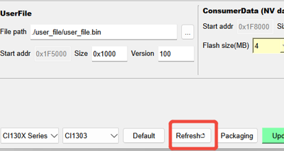
(6)UserFile (Command Word Information Table Storage Partition)
- File Path: ./user_file/user_file.bin. Or click the ellipsis icon on the right to select
user_file.binin the project directory (CI11XX_SDK\sample\internal\sample_xxx\firmware\user_file). - Reserved Size: Increase or decrease in multiples of 0x1000, or keep the default.
- Current Version: Version number of User_File.bin, can keep the default.
- Add UserFile: Uncheck if
user_file.bindoes not need to be packaged.
(7)ConsumerData (NVDATA Storage Partition)
- Reserved Size: Increase or decrease in multiples of 0x1000, or keep the default.
- Flash Size: Currently supports FLASH sizes of 4M, 8M, 16M, and 32M.
(8)Button Functions
- Chip Selection: Select CI110X series chips, CI112X series chips, or CI13XX series chips.
- Restore Defaults: Reset all options on the interface to default values.
- Refresh Address: After modifying the reserved size of each partition, click refresh address, then package the firmware.
- Package Firmware: Generate the firmware file in the resource file directory.
- Firmware Update: Switch to the firmware programming page.
- Parent Directory: Return to the parent tool main interface.
- Exit: Exit the tool.
3.3. Firmware programming Functions
- Click the (Firmware Update) button on the main interface or the (Firmware Update) button on the firmware packaging page to enter the firmware programming page shown in the figure below.
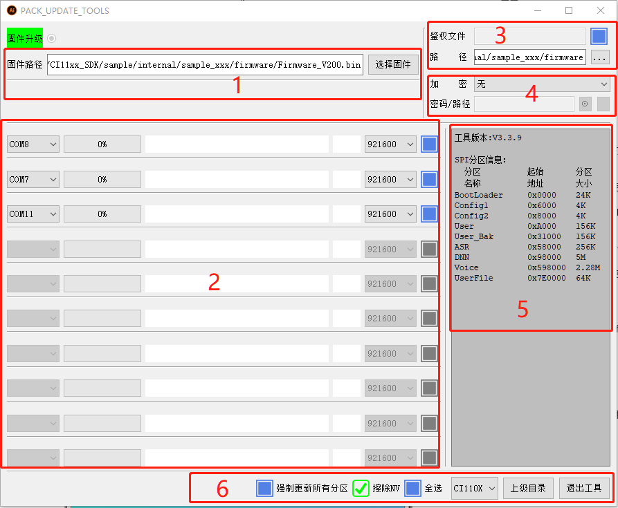
(1)Firmware Path
- Select Firmware: Select the path where the firmware is located.
(2)COM Port Selection Configuration and programming Progress Bar
- COMX: Select the COM number used by the USB serial port.
- %X: Firmware programming progress percentage.
- White Box: Text prompts during the programming process.
- Serial Port Baud Rate Selection: 115200 / 230400 / 460800 / 921600 / 1000000 / 2000000.
- COMX Number Selection Box: A green checkmark will be displayed after the COMX in use is selected.
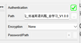
(3)Authentication File
- Authentication File: When checked, it will show how many authentication files there are. Authentication files are used for offline/online cloud connections.
- Path: Keep the default. Or select in the project directory (CI11XX_SDK\sample\internal\sample_xxx\firmware).
Note
The authentication file storage directory is: CI11XX_SDK\sample\internal\sample_xxx\firmware\authentication_file\valid\authentication file.
(4)Encryption
- Encryption: None/Standard Encryption/Custom Encryption Algorithm.
- Password/Path: When the encryption method is set to standard encryption, enter the password here. When a custom encryption algorithm is selected, select the algorithm file path here.
(5)Tool Version Information
- Includes tool version number and SPI partition information.
(6)Button Functions
- Force Update All Partitions: When checked, all partitions will be updated. If not checked, only the modified parts will be updated automatically.
- Erase NV: When checked, the NV information in FLASH will be erased during the upgrade.
- Select All: Version number of User_File.bin, can keep the default.
- Chip Selection: CI110X series chips/CI112X series chips/CI13XX series chips.
- Parent Directory: Return to the parent interface.
- Exit: Exit the tool.
4. Quick Start
4.1. Firmware Packaging
- Step 1: Enter the firmware packaging interface as shown in the figure below, fill in the Config configuration information, and use the default firmware partition information area content.

- Step 2: Click the (Package Firmware) button in the figure above. If the packaging is successful, the following prompt box will be displayed.
After clicking the (Package Firmware) button, if other error prompts appear, please refer to (Chapter 6 - Common Error Handling) to resolve the issue.
4.2. Firmware Update
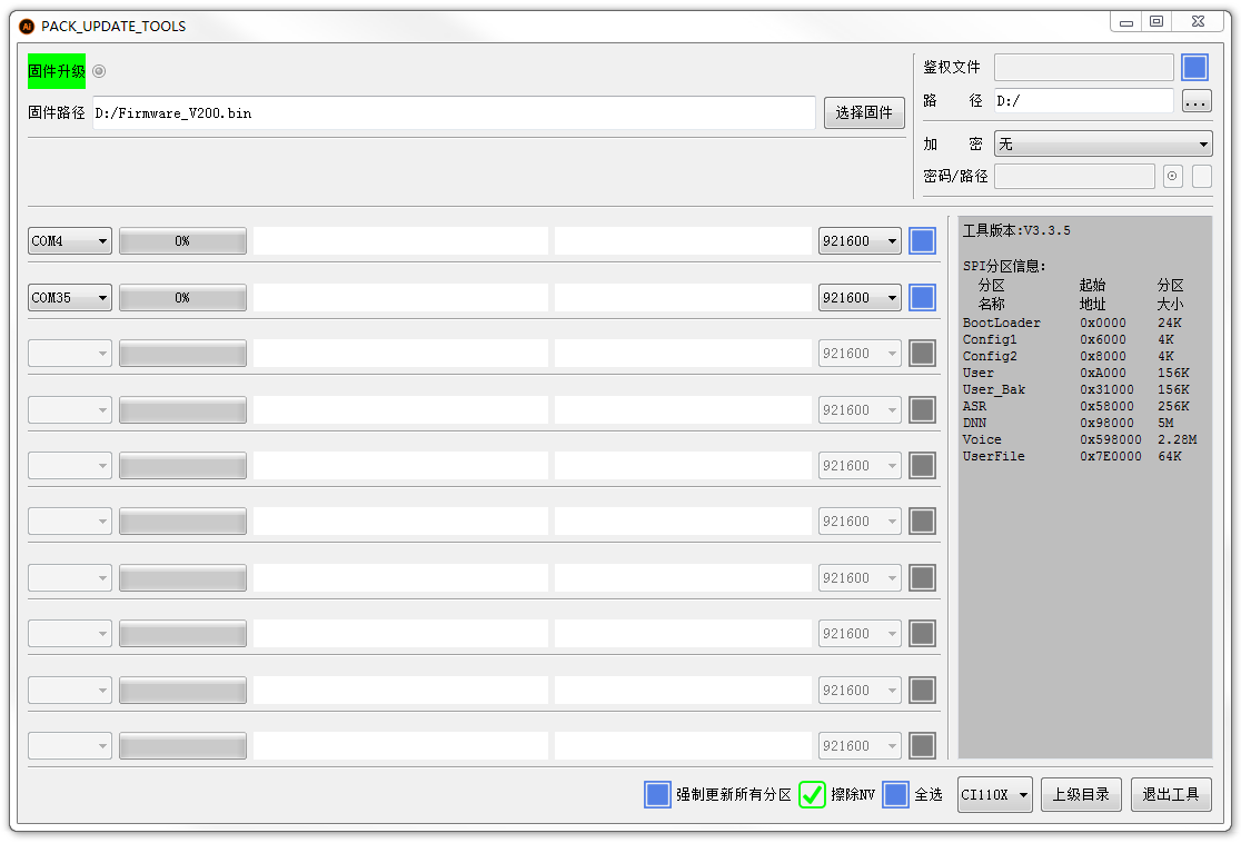
- Step 1: Enter the firmware programming interface as shown in the figure below.
- Step 2: Configure the following information.
(1) Select Firmware: Find the firmware that needs to be downloaded, which is the firmware packaged in Section 4.1 by default.
(2) Authentication File: Generally not needed for offline SDK. If needed for online SDK, please refer to Section 4.3 of this document.
(3) Encryption: Refer to the SDK document ☞《FLASH Encryption Function Quick Start》.
(4) Password/Path: Click the “eye” icon to display the password when using standard encryption. The “…” path can only be opened when using a custom encryption algorithm.
(5) Force Update All Partitions: Update all partitions including bootloader. If not checked, only the modified parts will be updated.
(6) Erase NV: Erase the original NV data stored in FLASH, selected by default.
(7) Select All: When performing a large number of upgrades, all serial ports can be selected.
- Step 3: Connect the hardware.
(1) At this point, you need to connect the board, plug in the microphone. The SDK defaults to UART0 as the programming serial port. Connect the USB TX to the board’s RX0, USB RX to the board’s TX0, and USB GND to the board’s GND. Use a jumper cap or DuPont wire to short the PG_EN pin to 3.3V to enter programming mode.
(2) After the corresponding COM number, you can modify the serial port baud rate. The default is 921600. Check the blue box after the corresponding COM number to select the serial port.
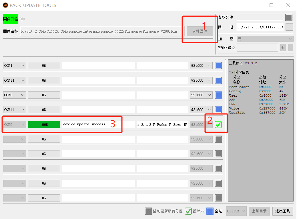
(3) After preparing the above steps, use the cold start method, that is, connect the USB 5V to the board’s 5V power interface, and power on to download the program. The successful download interface is shown in the figure below.
4.3. Authentication File
(1) The offline SDK generally doesn’t require authentication files, while the online/offline SDK does. After opening the UART tool PACK_UPDATE_TOOL.exe, an empty directory (authentication_file\valid) will be generated where you can place the authentication files.
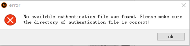
(2) The authentication file is used for offline&online solutions. When there are no authentication files in the authentication_file\valid directory, clicking the blue box after “Authentication File” in the firmware programming interface will show “0 authentication files” and prompt that no authentication files are available. If not needed, you can uncheck the authentication file option, as shown in the figure below.
(3) If you need to use the authentication file, store the authentication file in the authentication_file\valid directory. The total size of the authentication file cannot exceed 4K. After storing 3 authentication files in the authentication_file\valid directory, click the blue box after “Authentication File” to get the following result. At the same time, an empty invalid directory will be automatically generated in the authentication_file directory.
(3) After the programming is complete, the authentication file interface will display “0 authentication files”, indicating that the authentication files have been successfully programmed, and the authentication files in the valid directory will be moved to the invalid directory.
5. Common Error Handling
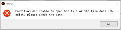
5.1. Partition User: Unable to open file or file does not exist, please check the path!
- If you see the following prompt, it usually means the program hasn’t been compiled yet, and user.bin hasn’t been generated.
-
For CI130X compilation instructions, please refer to the SDK documentation: ☞《CI13XX Series Chip SDK Quick Start》 (Section 4.3 Programming Method - Step 2).
-
After successful compilation, the application code’s user.bin will be generated in the CI11XX_SDK\internal\sample_xxx\firmware\user_code directory.
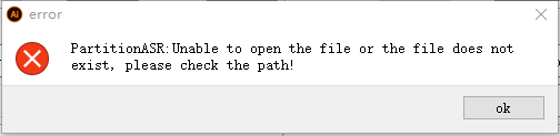
5.2. Partition ASR: Unable to open file or file does not exist, please check the path!
- If you see the following prompt, it means files like
asr.binhaven’t been generated yet (using the batch processing tool).
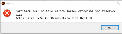
5.3. Partition User: File is too large, exceeds reserved size!
- If you see the following partition-related prompt, you generally need to adjust the User partition’s reserved size.
-
For example, if the actual User partition requires 0x28046 but only 0x26000 is reserved, you can increase the reservation by 0x3000 to 0x29000, and reduce another partition (DNN, ASR, or Voice) by the same 0x3000.
-
The reserved size must be configured in multiples of 0x1000. After adjusting the reserved size, remember to refresh the address.
-
If the customer has created many command words, you’ll typically need to increase the reserved size of the UserFile partition.
-
If all partitions have been adjusted to their limits and it’s still insufficient, it means the FLASH size cannot meet the requirements. You’ll need to either replace it with a larger FLASH or streamline resources in certain partitions. After changing the Flash, modify the Flash size according to the Flash model.
6. New Features
- With continuous version iterations and updates, several new features have been added to the latest version. The following sections describe these features in detail.
6.1 Added (Auto Allocate) Button in Packaging Interface
No need to manually set partition reserved sizes. Click the (Auto Allocate) button, and the tool will allocate partitions based on the sizes of files like asr.bin.
6.2 Added Chip Series and Model Selection Boxes to Each Interface
After selecting a chip series, the chip model dropdown will list all available chip names. You can then select your desired chip model.
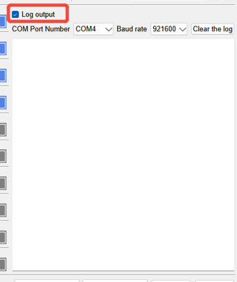
6.3 Added (Log Output) Window to the Upgrade Interface
Check the (Log Output) option to view program log output. You can select the baud rate and COM port, and there’s also a clear window function.