Electrical Characteristics
The electrical characteristic parameters of CI1306 are shown in the following table.
| Symbol | Description | Minimum | Typical | Maximum | Unit |
|---|---|---|---|---|---|
| VIN5V | PMU input pin voltage, generally 5V | 3.6 | 5 | 5.5 | V |
| AVDD | Analog and Codec power supply voltage | 2.97 | 3.3 | 3.63 | V |
| VDD33 | Chip IO power supply voltage | 2.97 | 3.3 | 3.63 | V |
| VDD11 | Chip core power supply voltage | 0.99 | 1.1 | 1.22 | V |
| VIH | Input high voltage, 3.0V ≤ VDD33 ≤ 3.6V | 0.7 * VDD33 | - | - | V |
| VIL | Input low voltage, 3.0V ≤ VDD33 ≤ 3.6V | - | - | 0.3 * VDD33 | V |
| VOL | Output low voltage @ IOL=12mA | - | - | 0.4 | V |
| VOH | Output high voltage @ IOH=20mA | 2.4 | - | - | V |
| I5VIO | Driving current when IO (5V withstand voltage) outputs 3.3V | 5 | - | 23 | mA |
| I33VIO | IO (3.3V withstand voltage) drive current when outputting 3.3V | 12 | - | 26 | mA |
| Σ IVDD | Sum of all IO total currents of the chip | - | - | 180 | mA |
| Pde | 5V power supply is adopted, 1.1V chip is powered by external DC-DC chip, and the total power consumption of 5V input during normal speech recognition (ambient temperature TA=25 ° C) | 75 | - | 175 | mW |
| Pdi | 5V is used to supply power to the chip, and the chip uses internal PMU. The total power consumption of 5V input during normal speech recognition (ambient temperature TA=25 ° C) | 165 | - | 265 | mW |
| RC oscillator accuracy 1 | TA=- 40 to 85 ° C | - 4 | - | +3 | % |
| RC oscillator accuracy 2 | TA=- 20 to 85 ° C | - 3 | - | +3 | % |
| RC oscillator accuracy 3 | TA=- 10 to 70 ° C | - 2.5 | - | +2.5 | % |
| Ta1 | The chip uses an external crystal oscillator to adapt to the working environment temperature | - 40 | - | +85 | ℃ |
| Ta2 | The chip uses an internal RC oscillator to adapt to the working environment temperature | - 10 | - | +70 | ℃ |
| Tst | Chip storage environment temperature | - 55 | - | +150 | ℃ |
The RC oscillator in the chip will produce a certain temperature drift with the change of ambient temperature.The greater the change of ambient temperature range, the greater the temperature drift. The temperature drift of the clock may affect applications that require high-precision clock or applications that require UART communication with MCU
If the application solutions requires high-precision clock, or UART communication with MCU is required, and the ambient temperature range exceeds - 10 to 70 ℃, it is recommended to use an external crystal oscillator as the clock source, and the working ambient temperature can meet or exceed the industrial standard specifications. If the internal RC oscillator is used as the clock source, the UART communication baud rate must be less than or equal to 115200bps, and the total deviation from the UART baud rate of the MCU shall not exceed 4% to ensure good communication. If the working environment temperature is - 10 to 70 ℃, the baud rate deviation of the matched MCU UART must not exceed ± 1.5% in this temperature zone. If the working environment temperature is - 20 to 85 ℃, the baud rate deviation of the MCU UART must not exceed ± 1% in this temperature zone
If the MCU is designed without a crystal oscillator, communication errors must be minimized. Chipintelli offers a UART baud rate auto-adaptation solution, which requires adding a handshake command to the UART protocol. The MCU must respond according to protocol requirements within 50 ms of receiving this handshake command. With this auto-adaptation mechanism in place, the product can reliably operate in environments ranging from -20°C to 85°C
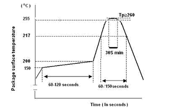
During SMT welding of CI1306, please control the temperature and time of the reflow. The temperature curve of a SMT welding is shown in the following figure.
The chip has a Moisture Sensitivity Level (MSL) of 3. Please store it according to MSL3 conditions before use. If the storage time after opening the package exceeds the MSL3 limit, baking is required before SMT soldering.