CI-D0XGS07J-BT Module Datasheet
Module Introduction
Overview
This module is a general-purpose, portable, low-power and high-performance speech recognition module developed for low-cost offline voice application solutions. The models include CI-D02GS07J-BT and CI-D03GS07J-BT. The pins of the two models are completely compatible, but the main chip models are different. The main chip of CI-D02GS07J-BT is CI1302, and the main chip of CI-D03GS07J-BT is CI1303. CI1303 has 2MB more Flash than CI1302, which can realize more command words and algorithm functions.
The module has the following characteristics:
The module features a compact design measuring 37mm × 40mm and operates at 5.0V-5.5V. It integrates a Bluetooth 5.0 chip and an audio power amplifier, supporting one microphone input and one speaker output. The UART interface operates at 5V logic level. The module can be powered directly through the 5V supply, with options for either standalone operation or integration with a main control panel. No soldering is required for UART communication or GPIO control. Two 3.5mm screw holes are provided for secure mounting.
Key Features
- Advanced Speech Processing: The main chip supports:
- Offline neural network computation
- Single-microphone noise reduction and enhancement
- Single-microphone echo cancellation
- 360° omnidirectional pickup
-
Environmental noise suppression for accurate recognition in noisy conditions
-
High Performance:
- 97%+ recognition accuracy
- <200ms response time for voice commands
- 10-meter recognition range
- No network dependency for offline operation
- Low Power Operation:
- Operating power consumption ≤ 0.5W
- Ideal for battery-powered applications
- Suitable for energy-efficient product designs
- Bluetooth 5.0 Connectivity:
- Low-power Bluetooth operation
- Supports audio streaming and hands-free calling
- Compatible with WeChat Mini Programs
- Seamless connection with mobile devices
- Industrial-Grade Reliability:
- Industrial-grade components
- Extensive reliability testing
- High temperature and humidity tolerance
- Suitable for demanding home appliance applications
| Module selection | Less than 200 local command words | 500 local command words |
|---|---|---|
| Single microphone offline speech Bluetooth module with socket | CI-D02GS07J-BT | CI-D03GS07J-BT |
Main Chip Introduction
The CI1302 and CI1303 are dedicated AI processors for speech processing, supporting:
- Local speech recognition
- Multiple language support (Chinese, English, Japanese, etc.)
- Applications in:
- Home appliances
- Lighting systems
- Consumer electronics
- Wearable devices
- Industrial controls
- Automotive systems
Technical Specifications
- Processor:
- BNPU V3 neural network processor
- Up to 220MHz CPU frequency
- 640KB SRAM
-
Integrated PMU and RC oscillator
-
Audio Processing:
- Dual-channel audio codec
- Low-power operation
-
High signal-to-noise ratio
-
Peripheral Interfaces:
- Multiple UART channels
- IIC, IIS interfaces
- PWM outputs
- GPIO pins
-
PDM interface
-
Design Advantages:
- Minimal external components required
- Cost-effective solution
- Simplified hardware design
For more details about CI1302 and CI1303 chips, please click the following link:
☞ CI1302&CI1303 Chip Datasheet
Application Scenarios
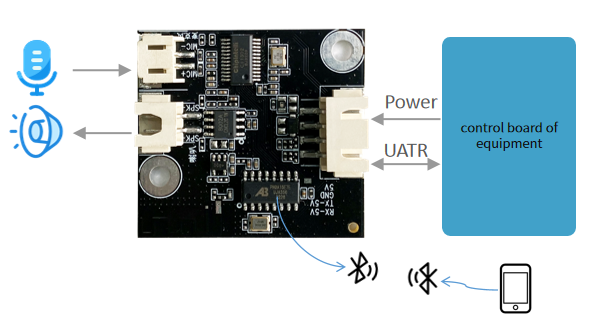
The CI-D0XGS07J-BT module offers flexible integration options:
-
Front-End Solution: * Voice recognition front-end paired with existing main control board * Requires external 5V power supply * External microphone and speaker connections
-
Standalone Solution: * Complete control module for end products * Ideal for lighting and toy applications * Simplified system architecture
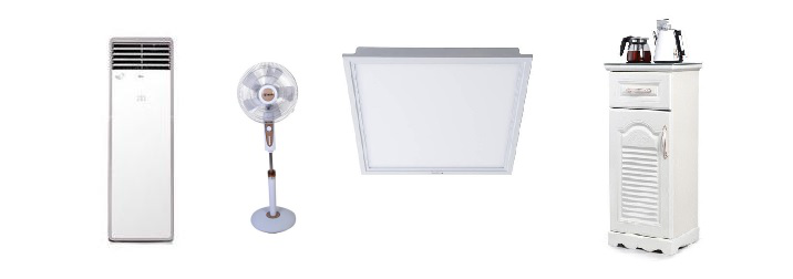
CI-D02GS07J-BT module supports up to 200 offline voice recognition command words, which can be applied to smart electric fans, heating tables, clothes dryers, small appliances, toys, lighting and other terminal products.
CI-D03GS07J-BT module supports up to 500 offline voice recognition command words, which can be applied to products requiring more command words such as air conditioners, washing machines and central control systems.
Module Specifications
Physical Layout
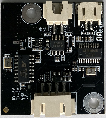
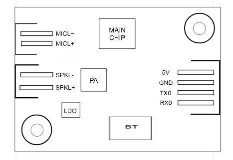
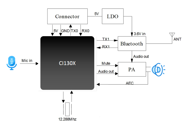
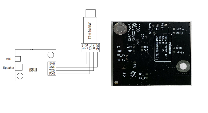
The physical module is shown in Figure 4. The speech recognition module is mounted on one side. The main IC includes speech recognition chip CI1302 or CI1303, audio power amplifier, Bluetooth, etc. The voice command is input from the microphone. After speech recognition and command processing by the speech recognition IC, the voice prompt is sent to the audio power amplifier to drive the speaker to play the sound. The maximum driving power of audio power amplifier is 1.1W@8 Ω and 2W@4 Ω. Acoustic echo cancellation is achieved through a Codec in the module. The maximum range of signal-to-noise ratio for effective echo suppression under normal operation is - 10dB to - 15dB.
Module Dimensional Drawings
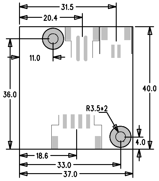
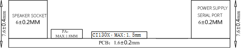
As shown in Figure 5, the module is rectangular in shape and 37 ± 0.3mm in size × 40 ± 0.15 mm, the PCB thickness is 1.6 ± 0.2 mm, and the module height is 7.6 ± 0.4 mm. Users can design the structure according to this size.
Pin Interfaces
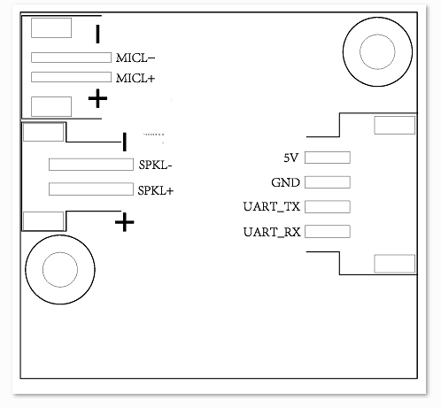
The pins of CI-D02GS07J-BT and CI-D03GS07J-BT modules are identical, and their positions are shown in the figure above.
This module has the following functional interfaces:
- Double wire single microphone interface, 2.0mm spacing bus port is used. To ensure good speech recognition effect, it is recommended to use a microphone with sensitivity of - 32 ± 3dB and signal-to-noise ratio of above 65dB. Please click ☞refer to microphone device for more information;
- Double wire single speaker interface adopts 2.5mm spacing bus port. In order to ensure good voice broadcast effect, it is recommended to use speakers with cavities. For more information, please click ☞refer to speaker device;
- Four wire power supply and UART interface adopt 2.5mm spacing bus port. Please refer to Figure 6 for the pin sequence. The UART pin in this interface can also be configured as a GPIO port in addition to serial communication.
The function description of all external pins of the module is shown in Table 2:
| Pin number | Pin name | I/O type | IO drive capacity | IO power on default state | Function definition |
|---|---|---|---|---|---|
| 1 | 5V | P | - | - | 5V power supply |
| 2 | GND | P | - | - | ground signal |
| 3 | UART_TX | IO,T+U | 4mA | IN,T+U | 1. GPIO PB5 2.UART0_TX 3.IIC_SDA 4. PWM channel 1 |
| 4 | UART_RX | IO,T+U | 4mA | IN,T+U | 1. GPIO PB6 2.UART0_RX 3.IIC_SCL 4. PWM channel 2 |
| 5 | MICL - | - | - | - | - |
| 6 | MICL+ | - | - | - | Positive pole of microphone |
| 7 | SKPL - | - | - | - | speaker positive output |
| 8 | SKPL+ | - | - | - | Speaker negative output |
The annotation symbols in the above table are defined as follows:
I input
O output
IO bidirectional
P power or ground
T+D tri-state plus pull-down
T+U tri-state plus pull-up
OUT power-on defaults to output mode
IN power-on defaults to input mode
Electrical Characteristics
| Parameter | Condition | Minimum Value | Typical Value | Maximum Value | Unit | Remarks |
|---|---|---|---|---|---|---|
| Module supply voltage | / | 5 | 5 | 5.5 | V | NOTE1 |
| Module Bluetooth broadcast status current | 4 Ω 3W speaker | / | 360 | 600 | mA | NOTE2 |
| Module working current | 5V power supply | 67 | / | 80 | mA | NOTE3 |
| Chip IO interface voltage | / | 5 | 5 | 5.5 | V | / |
| Module UART interface voltage | / | 5 | 5 | 5.5 | V | / |
NOTE1: 5V is the typical power supply voltage of the module. If the input voltage exceeds 5.5V, the module will be damaged. If the input voltage is lower than 5V, the Bluetooth chip may not work normally
NOTE2: The maximum current of the module in Bluetooth broadcast state can reach 600mA. According to the principle of double margin, it is required to provide a group of power supply with driving capacity of 1.2A for the module
NOTE3: Typical value is measured in mute state. Maximum value is measured during recognition and audio playback.
Environmental Specifications
The temperature and humidity parameters of CI-D02GS07J-BT and CI-D03GS07J-BT modules are consistent, as shown in Table 4.
| Parameter | Minimum Value | Typical Value | Maximum Value | Unit | Remarks |
|---|---|---|---|---|---|
| Module working ambient temperature | - 40 | 25 | 85 | ° C | / |
| Module storage environment temperature | - 40 | 25 | 100 | ° C | / |
| Module storage humidity | 0% | / | 5% | RH | / |
Module Application
Power-On and Startup
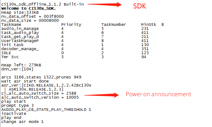
When using the module, connect the speaker and microphone, input the 5V power supply to the module through the power supply base, and the module will start after power on. When power on is normal, the speaker will broadcast a prompt audio. At this time, there will be print information on the UART port. The user can connect the UART port to the computer with USB-to-UART adapter and other tools. If the print information is seen in the UART debugging software in the computer, the module will start successfully, as shown in Figure 7. Note that the UART interface of the module is a 5V level high-speed serial port. It is no longer necessary to perform level conversion when interfacing with a 5V level system.
The 5V power supply of the input module will be directly supplied to the main chip. The audio power amplifier chip on the module is powered by 5V power supply. The rated power supply current of 500mA shall be guaranteed for 5V power supply. The power supply shall be stable and the ripple shall be within 100mV.
Module Default Command Word
If it is a user’s mass production module, the firmware of the command term specified by the user will be flashed before leaving the factory. If not specified by the customer, the module will have its own default firmware with default command words for user testing, as shown in the following figure:

Module Default UART Protocol
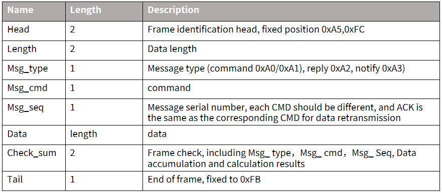
The module for programming general firmware supports UART communication, which is used for communicating with the MCU or other system. The protocol of the UART port is extensible, and has the following characteristics:
- Complete transmission package, including header and footer, length, verification, message type, and message serial number.
- Support variable length commands for easy expansion.
- Message type (command, notification, reply).
- Command message, configurable, reply to ACK. The notification message has no ACK.
- The message format will be the same as that of the bootloader upgrade, which is distinguished from the bootloader protocol through the header.
- The default baud rate is 9600.
- Note: Only UART0 interface is reserved for the module, and UART0 interface is the print output interface by default. If UART0 is required as the above UART protocol interface, the code must be modified, and the modification method can be implemented by referring to the UART protocol part of the documents in the ☞CI130X chip SDK.
- Supported commands: query the protocol version number, query the system version number, set the volume (the volume rating is defined in user_config.h), play the local broadcast, reset commands, etc. The specific protocol format is shown in the following figure:
Example 1:
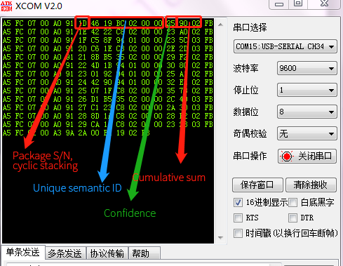
A5 FC 07 00 A0 91 18 01 55 E0 01 00 00 1B 9B 02 FB is resolved as follows:,
A5 FC:head
07 00: Valid data is 7byte
A0: This is the command word information
91: The command number is 0x91 (this data content is command word data)
18: Packet serial number, the 0x08th outgoing data of this serial port, which is continuously accumulated
01 55 E0 01 00 00: semantic ID, UNIQUE
1B: Command word threshold
9B 02: Cumulative Sum
FB: End data
Note: If only command words and thresholds are concerned in the application, only 7 valid data in the blue part can be concerned.
Example 2:
A5 FC 02 00 A3 9A 17 00 B1 05 02 FB is resolved as follows:
A5 FC :head
02 00: Valid data 2byte
A3: currently notification data
9A: The command number is 0X9A (the data content this time is the voice module content change)
17: This serial port sends data for the 0x07th time, and the value is continuously accumulated
00 B1: Valid data. (This data indicates entering the wake-up state)
05 02: Cumulative Sum
FB: End data
Note: This data is notification data, and the user can choose to use this information according to the situation.
For more content analysis data, please refer to the UART protocol part in ☞CI130X chip SDK. The following figure is a reference screenshot of protocol data:
Software Development Guide
If the default firmware of the module cannot meet the user’s needs, the user can develop the software by himself and modify the command words, voice prompts, UART protocol and other functions of the module.
The software development process mainly includes the following steps:
- SDK development kit material download
- Model making (language model+acoustic model)
- Speech synthesis
- The command word information table is associated with the audio file
- Firmware packaging
For detailed development process, please click ☞CI130X chip SDK.
Firmware Flashing
Preparation before Flashing
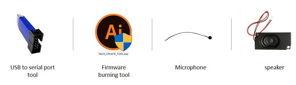
Before flashing the module, users need to prepare the following items:
- CI-D0XGS07J-BT module
- USB-to-UART debugging tool and USB-to-UART debugging tool driver
- Firmware flashing tool (pack_update_tool. exe)
- Firmware information (files in *. bin format)
- Microphone with 2.0mm pitch
- 2.5mm pitch speaker
- Several Dupont lines
Hardware Connection and Flashing
As an example of the USB-to-UART debugging tool shown in the above figure, the power, ground and serial port transceiver pins of the USB-to-UART debugging tool need to be connected with the corresponding pins of the module before flashing (note that the RXD and TXD of the USB-to-UART debugging tool correspond to the UART0_TX and UART0_RX of the module respectively). The connection method is shown in the following figure. The wiring diagram of module flashing and the chip marking diagram on the back of the module are shown in the figure below.
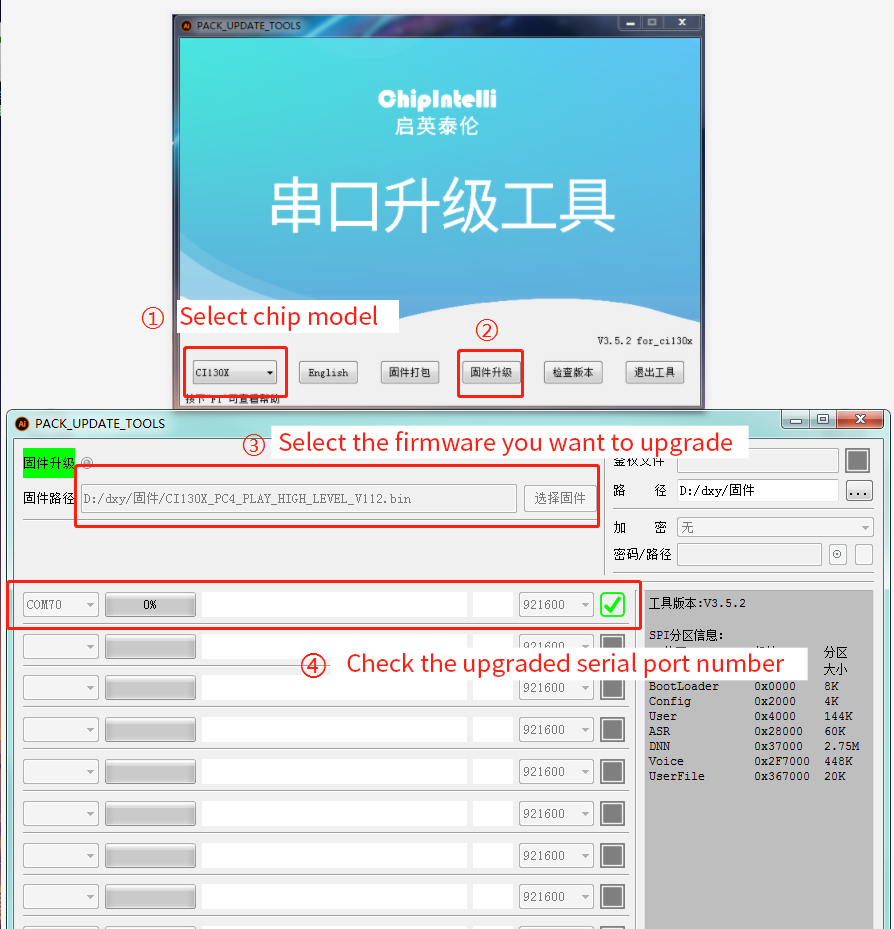
Open the firmware flashing tool (this tool can find PACK_UPDATE_TOOL.exe in the CI130X_SDK tools directory of the SDK development kit), select the corresponding model according to the chip, click the Firmware Update button, select the prepared firmware file, and confirm the serial port number assigned by the computer to the USB serial debug tool. After the module is powered on, it can enter the Firmware Update mode and start downloading firmware. If the computer cannot recognize the USB to serial debug tool, please install the corresponding driver first, and then apply 5V power to the voice module after completing the operation as shown in Figure 13 below.
- For the flashing of Bluetooth firmware, please refer to ☞Bluetooth firmware flashing method
Function Test
*Voice multi-function test: After the firmware is programmed, it is recommended to perform a function test on the module to verify whether the firmware is successfully programmed. Before the function test, the module to be tested needs to first connect the microphone and speaker, power on to confirm whether there is a power on voice prompt, and use the wake-up word and command word to test whether there is normal wake-up and recognition. If the module functions normally, the flashing is successful; Otherwise, the flashing fails, and further investigation is required.
- Bluetooth media playback function test:
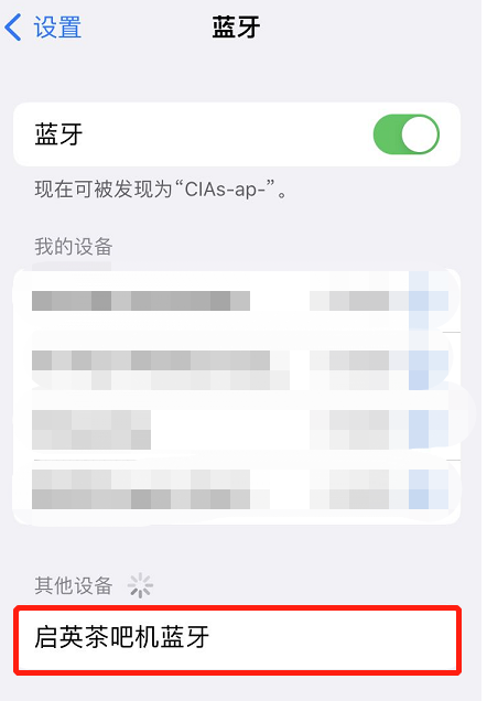
- After the module is powered on, the Bluetooth function is automatically turned on. After the phone turns on Bluetooth, the Bluetooth device named “Chipintelli Tea Bar Machine Bluetooth” can be found, as shown in the following figure:
- Click the “Chipintelli Tea Bar Machine Bluetooth” device to connect to Bluetooth, and then it will display connected, as shown below:
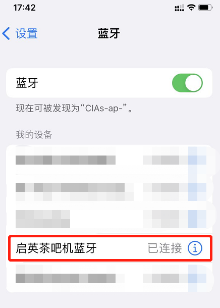
- From now on, you can play audio with your mobile phone player, and then play it through the module speaker.
- Telephone answering function test:
- After the module is powered on and the mobile phone is connected to Bluetooth according to the above operation.
- Answer the phone: When there is a phone connection, you can answer the phone through the voice module by directly saying “Answer the phone” to the voice command.
- Hang up the phone: When answering a call through the voice module, directly say “Hang up the phone” to the voice command, and the hang up operation will be automatically performed.
- Function test of saving and dialing:
- At present, only saved calls or fixed emergency calls can be made. Please refer to Figure 8 for relevant command words.
- Save the phone: The mobile phone is connected to the voice module Bluetooth. When you answer or make a call, wake up the voice module and say “Save the phone number”. At this time, the broadcast “OK, the phone number is saved” indicates that you have saved successfully.
- Make a call: The mobile phone is connected to the voice module Bluetooth, and after waking up the voice module, say “Call friend XXX” (note to save the number by step 2 first). At this time, the corresponding call will be made through the mobile phone.
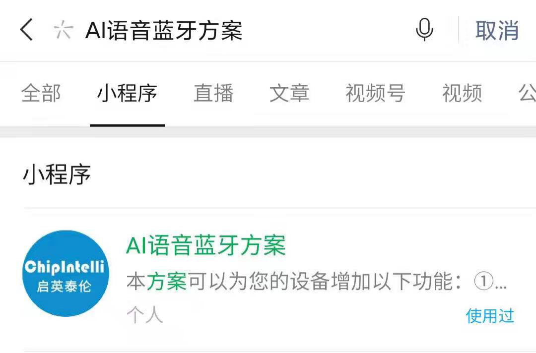
- Mini program control device:
- After the module is powered on, use the WeChat mini program to search for “AI voice Bluetooth solution” or scan the QR code, as shown below:

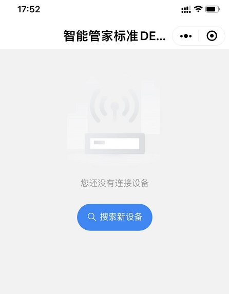
- Click the mini program to enter the interface as shown in the figure, and click to search for new devices, as shown in the figure below:
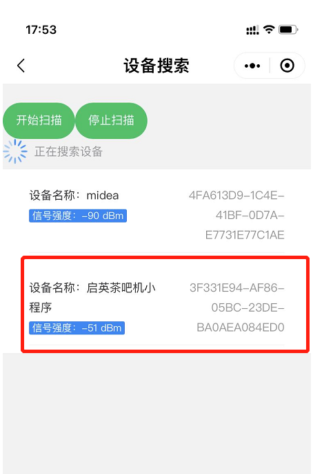
- Click “Search for new device” to see the interface as shown in the figure. Click to connect “Chipintelli Tea Bar Machine Mini Program”, as shown below:
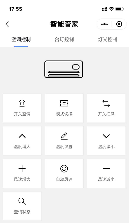
- After successful connection, the mini program will automatically enter the control interface. At this time, you can click the key to control the device, as shown below:
Troubleshooting
This chapter lists the problems that may be encountered in the use of some modules and the corresponding solutions.
The module cannot flash the updated firmware.
- Whether the UART pins are connected correctly, whether the TX and RX are connected reversely, whether the USB-to-UART debugging tool and driver at the computer is normal, and whether the PC flashing tool has selected the correct UART number;
- Whether the power supply is connected to the wrong voltage or position, causing chip damage;
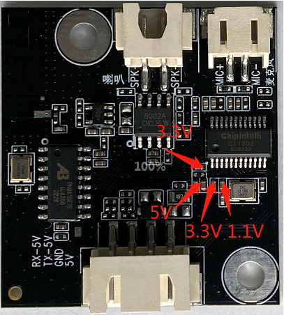
- If the module still cannot be flashed after checking the above two points, you need to use a multimeter to measure whether the module voltages of 5V, 3.3V and 1.1V are correct. Refer to the following figure for each hardware measurement point. If a voltage problem is found, it is considered as a module hardware failure. Replace the module or repair the module hardware. If there is no problem in the above inspection, please contact our technical support personnel for help.
The module is flashed, but there is no voice prompt after power on.
- Confirm whether the firmware matches the board;
- Confirm that the speaker is correctly connected and the power supply is normal;
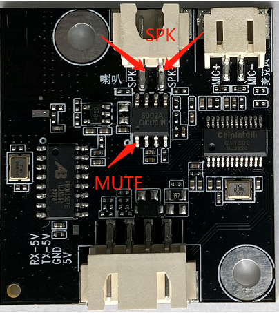
- Use a multimeter to test whether the voltage of MUTE pin of power amplifier is 0V; Whether the voltage of SPK+and SPK - to ground is about 2.5V. If the MUTE pin has a voltage of more than 1V, please confirm whether the level setting of the MUTE pin of the software is correct. If the MUTE pin has a voltage of 0V and SPK+or SPK - to ground has no voltage, please confirm whether the power amplifier has welding problems or replace it. The measuring points are shown in the figure below. If there is no problem in the above inspection, please contact our technical support personnel for help.
After the module is programmed, the command word is announced but not recognized after power on:
- Check whether the connection between the microphone and the socket is intact or replace a microphone;
- Check whether the positive and negative pole directions of the microphone are consistent with the markings on the module board and are not inserted reversely;
- Observe whether the board hardware has physical damage. If there is no problem in the above inspection, please contact our technical support personnel for help.
Bluetooth cannot be connected after the module is powered on:
- Observe whether there is physical damage to the board hardware;
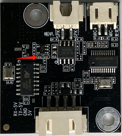
- Use a multimeter to measure whether the Bluetooth power supply is about 3.6V. The measuring points are shown in the figure below. If there is no problem in the above inspection, please contact our technical support personnel for help.
Other Application Precautions
Due to the high ESD rating of the CI1302 and CI1303 chips and the module’s design for easy user expansion, ESD protection components are only placed at the microphone interface on the module. For products with higher ESD protection requirements, additional ESD components may be added as needed. It is recommended that users wear anti-static wrist straps, gloves, or finger cots during inspection and soldering processes. Please also reserve ESD protection components at the corresponding connector positions on the baseboard to ensure product quality and reliability.
When using the module, make sure the microphone, speaker, power supply, and serial port are connected correctly. Avoid short circuits at the test points on the back side of the module.
Note that the module’s serial port operates at a 5V logic level. Please use a 5V-level serial interface for communication. Users can debug software by using a USB-to-UART Debugging Tool. During debugging, add serial print commands in the appropriate locations within the SDK, compile the firmware, and flash it to the module to perform debugging and validation.
Module Production&Storage Guide, Ordering Information
Production and Storage Guide
This module adopts an integrated terminal interface design, making production simple and convenient. To use the module, simply insert the microphone, speaker, and power/communication connectors into their corresponding terminals. The board features fool-proof interface design, ensuring there is no possibility of incorrect insertion between the three terminals.
During the insertion process, please wear anti-static gloves and an anti-static wrist strap. Apply appropriate force to ensure the connectors are fully seated. Open the vacuum-sealed anti-static packaging bag only when assembly is about to begin.
Storage Conditions
The module is vacuum packed, so the requirements for storage conditions are not high, and it can be stored in a non condensing atmospheric environment of<40 ℃/90% RH. The humidity sensitivity level MSL of the module is level 3. After the vacuum bag is unsealed or leaks, please control according to the humidity sensitivity level 3.
Ordering and Packaging Information
| Product model | Packaging method | Number of modules per pallet | Number of modules per package | Number of modules per box |
|---|---|---|---|---|
| CI-D02GS07J-BT CI-D03GS07J-BT |
Tray+electrostatic bag+carton | 40pcs | 400pcs for 10 trays | 1200pcs for 3 bags |
Procurement and Technical Support
If the user wants to purchase our product samples, please click on ☞Sample and Bulk Purchase to obtain more information.
If you want to obtain technical support, please log in to ☞Chipintelli AI Speech Development Platform.