Acoustic Echo Cancellation (AEC) Instructions
AEC is the abbreviation of Acoustic Echo Cancellation. With reference, this algorithm adaptively tracks the transformation of echo path and suppresses the echo signal of speakers arriving at the microphone terminal in real time to improve the recognition effect of target speech, and evaluates whether to turn on AEC according to the actual application scenario. When this function is enabled, voice recognition can also be interrupted when there is a long playing content or when playing audio media resources (such as MP3 songs played by speakers). This document mainly describes how to use this function.
1. AEC algorithm
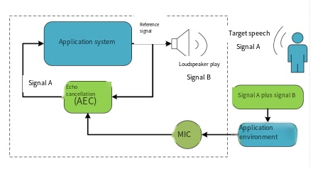
The block diagram of AEC’s application principle is as follows: the reference signal generates broadcast signal B through the speaker, and the voice is the target voice signal A. When playing the voice, signal B and signal A enter the chip after complex mixing in the application environment. The AEC algorithm suppresses signal B according to the reference signal and the mixed signal, improves the signal-to-noise ratio of signal A, and then enters the speech recognition engine to improve the recognition effect.
2. Software configuration method of AEC
Users can open the ci_ssp_config.c file in the SDK package. The echo cancellation algorithm provides the following parameters for debugging and configuration:
aec_config_t aec_config =
{
  .mic_channel_num = 1, //Number of microphone signal channels
  .ref_channel_num = 1, //Number of test signal channels
  .aec_control_mode = ENABLE_PLAYING_STATE_MODE, //ENABLE_PLAYING_STATE_MODE:Conduct aec control according to broadcast status; COMPUTE_REF_AMPL_MODE: perform aec control according to the reference amplitude
  .aec_gain = 4.0f,     //Gain value
  .aec_enable_threshold = 3000.0f,//Threshold value of reference signal judgment

  .nlp_flag = 2,        //The non-linear processing module selects the mode. By default, mode 2 is used. 0: Not used. 1: Mode 1 has greater distortion. 2: Mode 2 has less distortion. 3: Mode 2 is used first, then Mode 1

  .aggr_mode = 1,       //Default 1
  .fft_size = 256,      //Frequency number of frequency domain processing

};
Note
Pay attention to dual channel stereo application: modify parameters ref_channel_num 、mic_channel_num
3. Application configuration method of AEC
The AEC reference signal (and the signal played by the speaker) has the following two sources:
-
1: Refers to the speaker playing of the voice module itself, which is called internal AEC for short**
-
2: Refers to the speaker sound playing from other external players. This application is called external AEC for short**
3.1 Precautions for use of internal AEC
3.1.1 Hardware circuit description
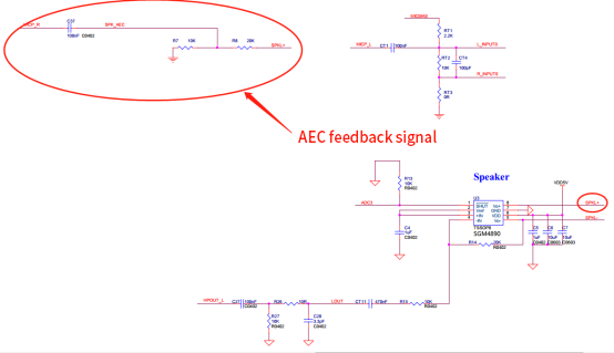
In the single microphone solution, another unused codec channel (micpr) of the CI110X chip is used as the AEC reference signal input channel.
In the case of low volume, AB power amplifier is recommended, such as SMG4890; Class D power amplifier is recommended for high volume.
AEC feedback signal is standard I2S, 16bits 16K sampling rate, full amplitude voltage 3.3V, then the voltage amplitude range after the reference voltage divider circuit is 100-150mv at the maximum volume.
3.1.2 matters needing attention
If the hardware is designed by your company, we can assist you to check the schematic diagram.
In case of stereo dual channel, dual channel codec shall be used to process the stereo after recovery as AEC reference signal
If Class D power amplifier is adopted, filtering circuit shall be added (refer to Class D power amplifier filtering circuit in subsequent external AEC ).
3.2 Precautions for use of external AEC
In the external AEC application, if it is a single mic application, the external reference signal can be input from MIC R in the form of analog signal; If it is a dual mic application, the external codec is required to pick up the reference signal. At the same time, the different signal output types (digital and analog) of the power amplifier will lead to inconsistent peripheral hardware lines. The following describes how to apply it according to the classification of the power amplifier.
3.2.1 Power amplifier output analog signal
(1) Hardware principle
AEC reference signal is standard I2S, 16bits 16K sampling rate.
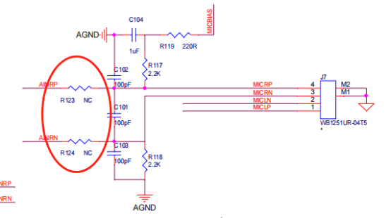
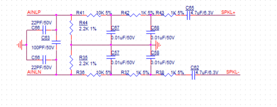
The output signal of the power amplifier is analog signal (such as Class AB power amplifier), and the reference signal path uses adc (Shunxin es7243E, single ended input) as the sampling of the reference signal (as shown in the following figure). The full amplitude voltage is 3.3V, and the voltage amplitude range after the reference voltage divider circuit is 100-150mv at the maximum volume.
The voltage divider circuit can refer to the following figure:
Synchronize the player’s playing status to the AEC module:
In sample internal sample_XXX\src\system_msg_deal. Check in c_current_Playing is a function for the aec module to obtain the playing state. The external player needs to inform the aec module by GPIO (or changing the playing state variable through the serial port).
The following is the routine of informing the aec module in GPIO mode: (When playing music, the external player pulls up the pin of the corresponding GPIO, and when stopping playing, pulls down the pin of the GPIO):
bool check_current_playing(void)
{
    //  if(AUDIO_PLAY_STATE_IDLE != get_audio_play_state()) //Inform aec module status during internal playback
    if(gpio_get_input_level_single(GPIO2,gpio_pin_7)==1)//When it is high, the external player is playing
    {
       return true;
    }
    else
    {
       return false;
    }
}
3.2.2 Power amplifier output digital signal
(1) Hardware principle
AEC feedback signal is standard I2S, 16bits 16K sampling rate.
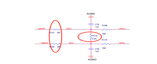
The output signal of the power amplifier is digital signal (such as Class D power amplifier), and the reference signal path uses adc (such as AD51050, Shunxin es7243E, differential input) as the sampling of the reference signal (see the figure below). The full amplitude voltage is 3.3V, and the voltage amplitude range after the reference voltage divider circuit is 100-150mv at the maximum volume.
The voltage divider circuit can refer to the following figure:
If the product (or voice module) plays stereo audio with dual channels, it needs to go through a dual-channel codec before connecting to the power amplifier.
Synchronize the player’s playback state with the AEC module:
When using ENABLE_PLAYING_STATE_MODE, the external playback state needs to be synchronized. Set the playback state commands as follows:
ciss_set(CI_SS_PLAY_STATE, CI_SS_PLAY_STATE_PLAYING);  // Set current state to playing
ciss_set(CI_SS_PLAY_STATE, CI_SS_PLAY_STATE_IDLE);     // Set current state to idle (not playing)
4. Precautions and influencing factors of AEC effect
4.1 Precautions for reference signal
Avoid reference analog signal saturation
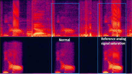
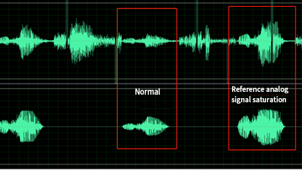
Debugging suggestion:The signal in front of the voltage divider circuit is distorted, and the volume of, or should be adjusted or replaced with a low impedance speaker.
The reference analog signal of AEC is a small analog signal, which is easy to be interfered. Special attention should be paid to the cleanliness of the reference signal during layout. When designing, the reference analog signal should be as far away from the high-frequency signal as possible. If there is a problem in the circuit design, bad signals, such as pulses, clutter, and aliasing, are usually introduced into the collected signal or microphone signal, which will lead to data loss and affect the effect.
Debugging suggestion:In this case, the hardware circuit design should be modified first to ensure that the circuit signal is clean before the acoustic test. The interference of the reference signal has a significant impact on the AEC effect.
The reference signal collected from the back end of the power amplifier is the closest to the real sound of the speaker. When the power amplifier has no delay, the front-end signal of the power amplifier can be used as a reference. When the power amplifier has delay (especially some power amplifiers with eq), it is recommended to take the reference signal from the back-end of the power amplifier. If the signal is introduced from the back end of the PA, pay attention that the output range of the power amplifier should not exceed the ADC sampling range.
4.2 Precautions for mic signal
Avoid intercepting the collected mic voice signal
Debugging suggestion: play the full sweep signal at the maximum volume of the speaker, the speaker shall not have broken sound, resonance, etc., and the mic acquisition signal and reference signal shall not have clipping. Excessive speaker will lead to more serious distortion. In practical application, it is necessary to select an appropriate volume range (speaker is not distorted).
4.3 Precautions for speaker
The reduction of harmonic distortion is due to the fact that the system is not completely linear. In the whole audio channel, the influencing factors of signal harmonic distortion include: distortion curve of single speaker, structural design of speaker rear cavity, speaker front mesh, microphone receiver hole structure, etc; All of these will increase the distortion of the microphone signal. The greater the distortion of microphone signal, the worse the similarity between microphone signal and recovery signal, and the worse the performance of echo cancellation. The frequency response of the speaker has poor consistency at 200~4khz, and the structure has resonance, which will affect the AEC effect.
Generally, speakers have a certain degree of distortion. When the volume is close to the speaker’s playback limit, the distortion will be increased. Try to make the speakers work in a small range of distortion when they are used. Different speakers will have different fixed distortion interference.
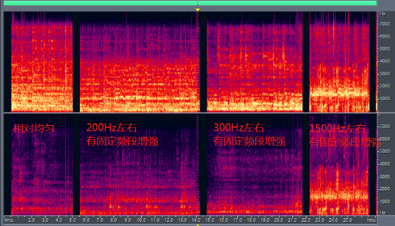
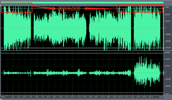
The speakers with low distortion should also be selected. Refer to Figure 4-3-1. The following figure shows the sound played by the four speakers. As can be seen in the figure, some speakers have large distortion in different frequency bands, such as the last three in the figure below. The speech distortion in these different frequency bands will seriously affect the AEC effect, so try not to use such speakers. The first speaker in Figure 5-5 has good frequency response.
When using the speaker, avoid the top clipping of the microphone signal caused by excessive speaker sound.
Debugging suggestion: Try not to use micro speakers, ultra-thin speakers and other speakers with high resonance frequency, because such single units have large low-frequency distortion; If the rear cavity structure of the speaker allows, the design of passive radiator or guide tube can increase the low frequency and reduce the nonlinear vibration of the speaker.
4.4 Environmental precautions
Reduce mechanical noise In household appliances, robots and other products and equipment, the variable introduced by fan noise and motor noise will cause the bottom noise of microphone signal to be particularly large, and the recognition effect will be greatly affected.
Debugging suggestion: In this kind of equipment, special attention should be paid to the distance between the internal fan, motor and microphone. If the structure space allows, the microphone can be sealed separately to prevent internal sound transmission.
4.5 Position relationship between microphone and speaker
- Debugging suggestions: the position relationship between the microphone and the speaker. In principle, if the structure space allows, the microphone should be as far away from the speaker as possible. The microphone should not exceed the horizontal plane where the speaker faces. The closer the microphone is to the speaker, the lower the signal-to-noise ratio, the greater the possibility of microphone distortion. Considering the structure size, it is recommended that the microphone be about 10cm away from the speaker, The position relationship between microphone and speaker has little influence on AEC processing effect.
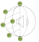
- Ensure the speaker output is directed away from the microphone, avoiding direct alignment with it.
5.Method of debugging AEC
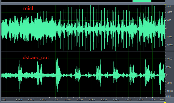
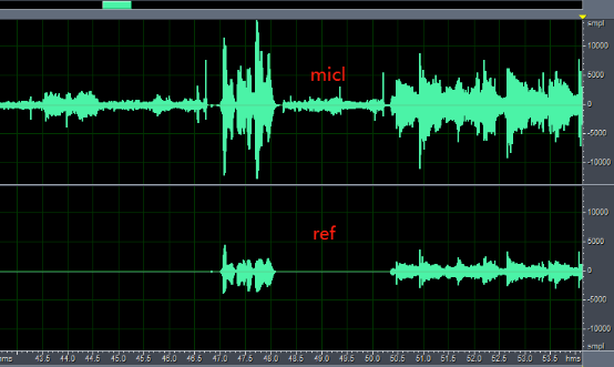
Figure 5-1 shows the time domain effect of sound acquisition of the recording board. It can be seen from the figure that the original left channel data (the upper half figure) is a mixture of the target voice and the speaker playing voice. After the aec algorithm processing, the speaker playing voice is suppressed and the signal-to-noise ratio of the target voice is improved, as shown in the right channel data (the lower half figure) in Figure 5-1.
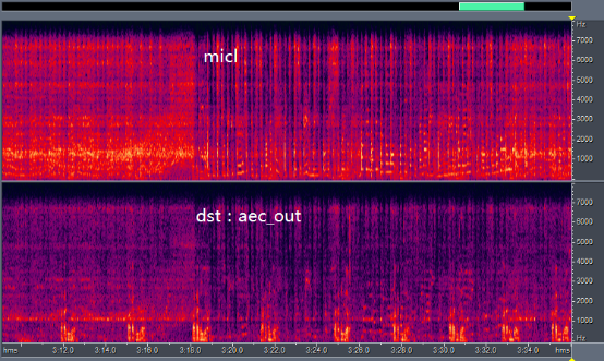
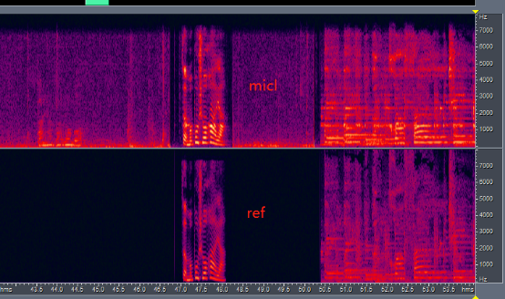
The following figure 5-2 shows the frequency domain display of the same audio, and the result is normal.
When setting the IIS output parameters to audio_pre_rslt_write_data((int16_t*)ref, (int16_t*)micl), the output includes reference signal data and left-channel microphone audio capture data, as shown in Figure 5-3. The figure illustrates that when audio is playing, the reference signal contains data, while when no audio is playing, the reference signal is minimal and close to zero.
Note
Try to ensure that the reference signal and microphone signal are not truncated or distorted.
6.Debugging steps for abnormal AEC
Note
In the process of debugging abnormal AEC, record and save the audio, which is conducive to rapid analysis by other colleagues.
When the application of aec does not meet the expectation, it is recommended to take standard sdk and hardware as reference, and analyze the specific reasons through reference sub module of standard accessories.
Step 1: Determine whether the sdk configuration is abnormal;
Step 2: Determine the cause of abnormality by collecting the reference signal (ref), output signal (dst) and microphone signal (mic) from the acoustic panel; At present, many abnormalities occur in the reference signal. Examples of existing problems are:
Abnormal reference signal:
-
1: The reference channel has no data, so it is necessary to check the hardware channel and whether ref is a left channel input or a right channel input. The default is the left channel
-
2: The reference signal interference is relatively large, so check the hardware path
-
3: The amplitude of the reference signal deviates from the standard value greatly (too large or too small), so it is necessary to check the voltage divider circuit and alc gain value, taking the standard board as a reference
-
4: In case of saturation during voltage division of reference signal, it is necessary to check the voltage division circuit and alc gain value, and AEC abnormal debugging cases
*Abnormal microphone signal:
-
1: In the process of aec processing, alc is not closed, so check the playback status and alc switching status
-
2: If the microphone signal is truncated, check the playback status, alc switching status and alc gain value
-
3: The microphone signal sensitivity is different, and the microphone needs to be replaced to confirm whether the microphone is abnormal
-
4: The amplitude of the microphone is too small, and the aec does not work. The threshold value in the aec processing needs to be adjusted and changed
Step 3: Replace different modules to analyze whether it is the difference of peripheral hardware devices that causes the abnormal peripheral devices: microphone, speaker, voltage divider, power amplifier, codec, etc;
Step 4: Check whether the aec effect is reduced due to environmental factors. If the reverberation is high, the aec effect will be reduced;
Step 5: If the above methods cannot effectively solve the problem, the algorithm colleagues will support it.