CI-D06GT01D Evaluation Kit
Overview
The CI-D06GT01D development board (hereinafter referred to as the development board) can be used for the development and debugging of CI130X series chips. The development board integrates a USB bus adapter chip CH340G, which can directly download programs for the chip through the USB interface. At the same time, the development board has many test interfaces and test circuits, which can help users develop products quickly.
Description of main resources of the development board
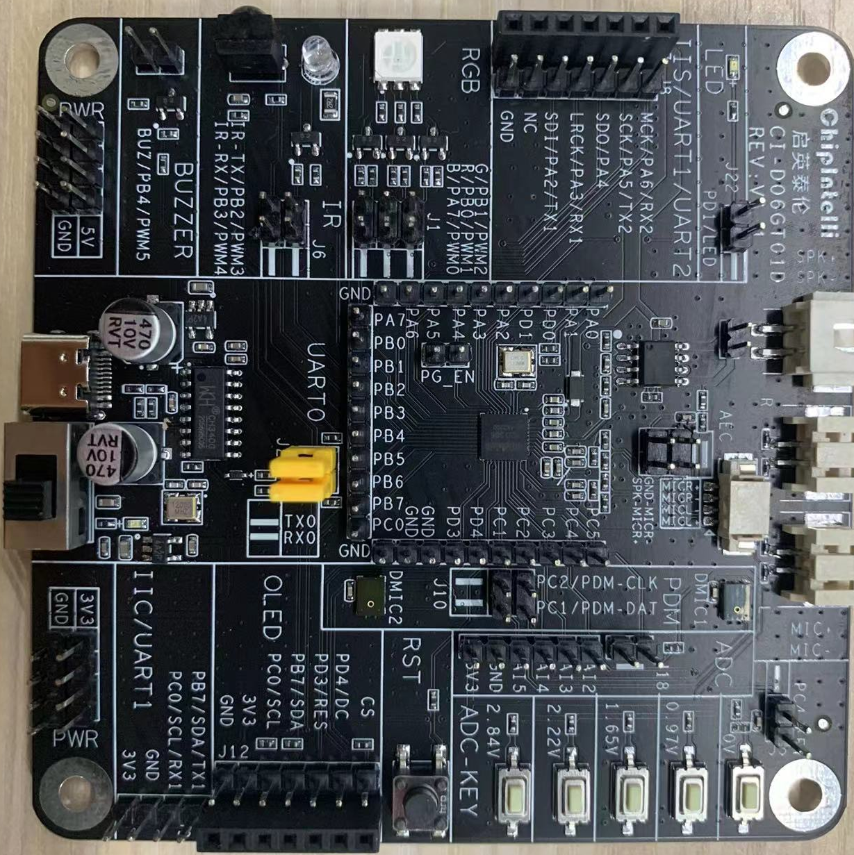
The development board includes the following resources:

- 1: USB to serial port
The development board integrates CH340G USB to serial port chip circuit, and is equipped with TYPE-C standard USB interface. The TYPE-C USB interface can be conveniently used to complete the chip flashing and UART0 communication functions, and can also be used as a power access terminal to power the development board.
update firmware using serial port UART0_ TX and UART0_ RX, there is an interface pin of this serial port on the development board. If you use TYPE-C to upgrade, you need to short-circuit this pin. If you use USB to serial tool to upgrade, you can use DuPont cable to connect with this interface pin.
- 2: Infrared transceiver circuit
The development board is equipped with red light emitting tubes, which can be used to develop voice infrared and other remote control devices.
- 3: RGB color lamp
The development board is equipped with an RGB color LED, which can realize full color display through the PWM port of the chip.
- 4: PDM digital microphone
The development board is equipped with two PDM digital microphones, which can be used for double microphone algorithm, speech recognition and other functions.
- 5: 5 ADC key circuits
The development board is equipped with five keys, and the key detection of five channels is completed by using the ADC sampling function of the chip.
- 6: 1-channel audio power amplifier
The development board is equipped with a Class A power amplifier, which can drive the 8W and 2W speakers to sound.
- 7: 2-way microphone input interface
The development board has a 2-way microphone analog interface, which can realize single or double microphone speech recognition, AEC and other functions.
- 8: IIS/UART/IIC/PWM/pin array interface
The development board leads out the digital interface of the chip, which is used to test the digital IO of the chip and expand other functional circuits.
- 9: PWM buzzer interface, which can be externally connected to test various buzzers.
If you need to have a more detailed understanding of the development board application, please refer to the following schematic file:
☞ Development Board Schematic Diagram Data
Application examples
The following describes the use of this evaluation kit by using a module board to flash standard firmware, wake up with voice, and control with voice.
Note: If the user purchases our CI-D06GT01D evaluation kit, there will be a factory firmware by default. The function that can be realized is: after recognizing the command word, the corresponding broadcast will be fed back through the speaker
Preparations
To complete this example, you need to prepare materials first, and the list is shown in Table 1.
| Name | Description | Quantity | Purchase Method |
|---|---|---|---|
| CI-D06GT01D | Development board | 1 | ☞sample purchase |
| Microphone | pickup | 1 | ☞sample purchase |
| speaker | Broadcast sound | 1 | ☞sample purchase |
| All pass TYPE-C cable | Connect computer flash firmware and power supply |
1 | Mobile phone data cable or self purchase |
Connection diagram
A physical connection diagram of the evaluation kit is shown in the following figure:
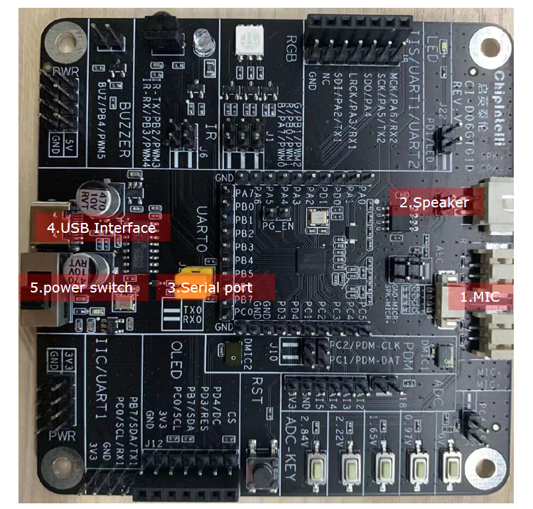
The connection method is as follows:
- Connect the TYPE-C USB to the USB 4 position in the figure;
- The microphone is connected to the seat of the red frame 1 in the above figure (note that the chip marking MIC+pair MIC+, MIC - pair MIC -);
- The speaker is connected to the seat of the red frame mark 2 in the above figure (no need to separate directions);
- The serial port is marked with position 3 in the short circuit diagram.
Operating Steps
After the evaluation kit is connected according to the above connection diagram, the following steps can be followed:
- One end of the TYPE-C cable is connected to the USB port of the computer or 5V charger, and the other end is connected to the power interface of the development board (at the place marked with 4 in the red box in the connection diagram);
- Turn on the switch (at the place marked with red box 5 in the connection diagram). When the light on the development board lights up, it indicates that it is powered on;
- After powering on, you will hear “Welcome to use Smart Fan, please use “Hello Jenny” to wake me up”. At this time, when you say “Hello Jenny”, you will hear “Hello” on the development board, representing that the module, power supply, microphone and speaker have been connected;
- In case of any abnormality, please contact our technicians for support.
Command words and corresponding broadcast of standard module
Our standard module has flashed the standard program before leaving the factory. When using it, you need to say the wake-up word “Hello Jenny” first. After hearing the broadcast of “Hello”, you can say other command words. When you hear “I am leaving, call me later”, the module is back to sleeping mode. You need to say “Hello Jenny” again to wake it up.
The following table shows the command words corresponding to one of our standard firmware: Note: Some command words may be deleted or added according to specific needs without notice

Application Considerations
For the method of flashing and debugging the development board, users can refer to the document CI130X Chip SDK, which contains instructions on how to flash and debug the development board.