CI-B02-MB Development Board Kit Description
Overview
The Chipintelli speech recognition module can form a corresponding development board kit with the special backplane CI-B02-MB (hereinafter referred to as the backplane). This backplane is a general backplane developed to realize the basic function demonstration, design, development and use of voice modules CI-B02GS04S, CI-B03GS04S and CI-C22GS02S (hereinafter referred to as voice modules) of Chipintelli. Through this backplane, the external connection and extended application of the supporting voice module can be realized, as well as the design verification of the user developed firmware.
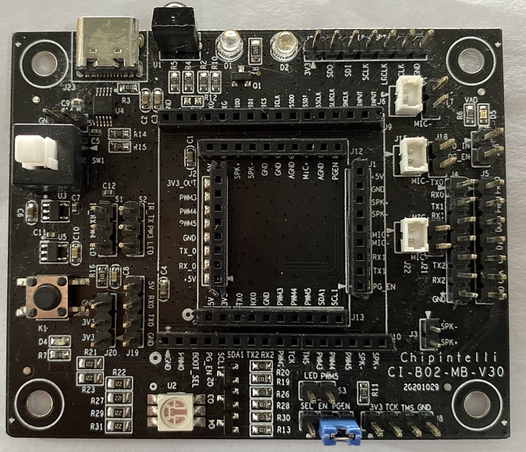
External view of base plate
The appearance of the base plate is as follows:
The backplane can select different modules according to the required functions, which can be used in conjunction with the module specification.
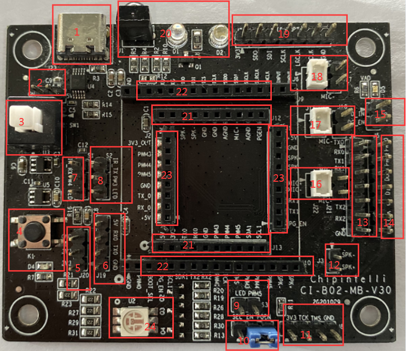
The functions of each interface of the backplane are defined as follows:
| Tag No. | Interface Location | Function&Definition | Description | Connected voice module model |
|---|---|---|---|---|
| J23 | 1 | TYPE-C interface | TYPE-C interface 5V power input firmware burning interface |
CI-B02GS04S CI-B03GS04S CI-C22GS02S |
| J14 | 2 | 5V (5V power supply interface) GND (grounding pin) |
2PIN-2.54 pin 5V power input |
CI-B02GS04S CI-B03GS04S CI-C22GS02S |
| SW1 | 3 | Backplane switch button | Press to turn off power Pop up to power up |
CI-B02GS04S CI-B03GS04S CI-C22GS02S |
| K1 | 4 | Extended key | Trigger function | None |
| J20 | 5 | 3.3V, 3.3V, GND | 3PIN-2.54 3.3V power output maximum output 50MA |
CI-B02GS04S CI-B03GS04S CI-C22GS02S |
| J19 | 6 | 5V (5V power supply input pin), RX0 (serial port 0 receiving), TX0 (serial port 0 sending), GND (grounding pin) |
4PIN-2.54 Spare firmware burning interface |
CI-B02GS04S CI-B03GS04S CI-C22GS02S |
| S1 | 7 | 3PIN-2.54 PWM4 function selection |
PWM4 and IR_ RX short circuit Select infrared receiving function, PWM4 and LED short circuit Select LED green light control function |
CI-B02GS04S CI-B03GS04S CI-C22GS02S |
| S2 | 8 | 3PIN-2.54 PWM3 function selection |
PWM3 and IR_ TX short circuit Select infrared sending function, PWM3 and LED short circuit Select LED blue light control function |
CI-B02GS04S CI-B03GS04S CI-C22GS02S |
| S3 | 9 | 2PIN-2.54 PWM5 function selection |
PWM5 short circuit with LED LED red light control function selection |
CI-B02GS04S CI-B03GS04S CI-C22GS02S |
| J11 | 10 | 3PIN-2.54 Debugging function selection |
Short circuit between EN and SEL Power on to enter BOOT debugging status, short circuit between EN and PGEN Power on to enter upgrade request status |
CI-B02GS04S CI-B03GS04S CI-C22GS02S |
| J8 | 11 | 4PIN-2.54 BOOT debugging pin |
3.3V (maximum output 50MA), TCK (JTAG_TCK), TMS (JTAG_TCKTMS), GND (grounding pin) |
CI-B02GS04S CI-B03GS04S CI-C22GS02S |
| J3 | 12 | 2PIN-2.54 Speaker interface |
Connected to 8R/2W or 4R/3W speakers | CI-B02GS04S CI-B03GS04S CI-C22GS02S |
| J4 | 13 | 7PIN-2.54 Serial interface |
TX0 (serial port 0 sends), RX0 (serial port 0 receives), TX1 (serial port 1 sends), RX1 (serial port 1 receives), TX2 (serial port 2 sends), RX2 (serial port 2 receives), GND (receiver pin) Note: Serial port 0 is connected with serial port 0 of J19 |
CI-B02GS04S CI-B03GS04S CI-C22GS02S Yes Serial port 0, 1 Serial port 2 has no voice module |
| J5 | 14 | 7PIN-2.54 Expansion function interface |
PWM0 (PWM0 interface), PWM1 (PWM1 interface), DOUT (expansion SPI interface), DIN (expansion SPI interface), CS (expansion SPI interface), CLK (expansion SPI interface), GND (grounding pin) |
None at present |
| J16 | 15 | 2PIN-2.54 Extended function interface |
D-IN (extended SPI interface), PG_ EN (the same function as the PGEN pin of J11) |
CI-B02GS04S CI-B03GS04S CI-C22GS02S D-IN has no voice module available |
| J21 J22 |
16 | 2PIN-2.54 2PIN-1.25 Microphone input port |
MIC+(positive pole of microphone), MIC - (negative pole of microphone) |
CI-C22GS02S |
| J15 J18 |
17 | 2PIN-2.54 2PIN-1.25 Microphone input port |
MIC+(positive pole of microphone), MIC - (negative pole of microphone) |
CI-B02GS04S CI-B03GS04S |
| J6 J17 |
18 | 2PIN-2.54 2PIN-1.25 Microphone input port |
MIC+(positive pole of microphone), MIC - (negative pole of microphone) |
No voice module can be connected temporarily |
| J7 | 19 | 7PIN-2.54 IIS interface |
3.3V (maximum output 50MA), SDO (IIS_SDO interface), SDI (IIS_SDI interface), SCLK (IIS_SCLK interface), LRCK (IIS_LRCK interface), MCLK (IIS_MCLK interface), GND (grounding pin) |
No voice module can be connected temporarily |
| J1 D1 D2 |
20 | Infrared sending and receiving | Using this function requires short circuit selection according to position interfaces 7 and 8 | CI-B02GS04S CI-B03GS04S CI-C22GS02S |
| J12 J13 |
21 | Module interface | Connected to voice module | CI-B02GS04S CI-B03GS04S |
| J9 J10 |
22 | Module interface | Connected to voice module | No voice module available temporarily |
| J1 J2 |
23 | Module interface | Connected to voice module | CI-C22GS02S |
| U2 | 24 | LED tricolor light | Using this function requires short circuit selection by position interface 7, 8, 9 |
CI-B02GS04S CI-B03GS04S CI-C22GS02S |
If you need to have a more detailed understanding of the backplane interface and its application, please refer to the following schematic file of the backplane:
☞ Schematic diagram data of the base plate
Application examples
The following describes the use of this development board kit by using a module board to burn standard firmware, wake up with voice, and control with voice.
Note: If the user purchases the samples of our CI-B02GS04S, CI-B03GS04S, CI-C22GS02S modules, there will be a basic firmware in them. The function that can be realized is: after identifying the command word, the corresponding broadcast will be fed back through the speaker
Preparations
To complete this example, you need to prepare materials first, and the list is shown in Table 2.
| Name | Description | Quantity | Purchase Method |
|---|---|---|---|
| CI-B02GS04S CI-B03GS04S CI-C22GS02S |
Voice module board | 1 | ☞sample purchase |
| CI-B02-MB | module base plate | 1 | ☞sample purchase |
| Microphone | pickup | 1 | ☞sample purchase |
| Horn | Broadcast sound | 1 | ☞sample purchase |
| All pass TYPE-C cable | Connect computer Burn firmware and power supply |
1 | Mobile phone data cable or self purchase |
Connection diagram
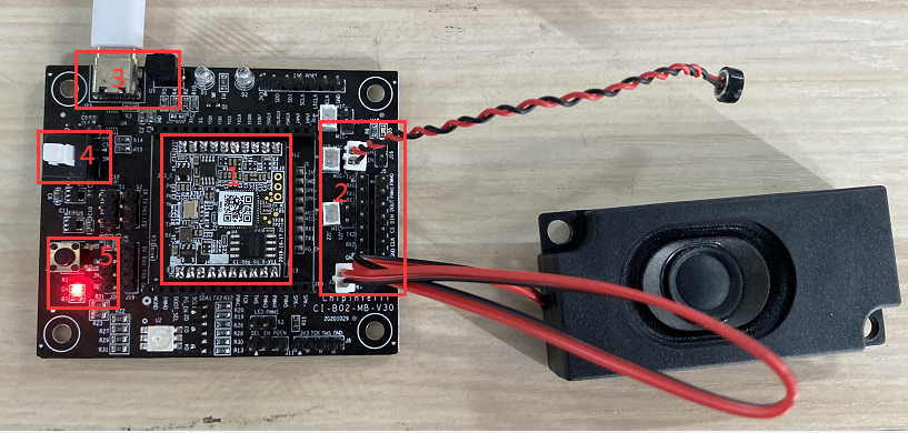
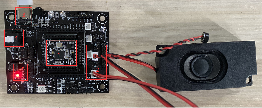
A physical connection diagram of the development board kit is shown in the following figure:
- Connection diagram when purchasing CI-B02GS04S and CI-B03GS04S modules
The connection method is as follows:
- Insert the CI-B02GS04S module board into the red box 1 in the figure above, and pay attention to the direction (the position of the CI-B03GS04S module is the same);
- The microphone is connected to the seat in the red frame mark 2 in the above figure (pay attention to the silk screen MIC+for MIC+, MIC - for MIC -);
- The horn is connected to the seat of the red frame mark 2 in the above figure (no need to separate directions).
- Connection diagram when purchasing CI-C22GS02S module
The connection method is as follows:
- Insert the CI-C22GS02S module board into the red box 1 in the figure above, and pay attention to the direction (the position of the CI-B03GS04S module is the same);
- The microphone is connected to the seat in the red frame mark 2 in the above figure (pay attention to the silk screen MIC+for MIC+, MIC - for MIC -);
- The horn is connected to the seat of the red frame mark 2 in the above figure (no need to separate directions).
Operating Steps
After the development board kit is connected according to the above connection diagram, the following steps can be followed:
- One end of the TYPE-C cable is connected to the USB port of the computer or 5V charger, and the other end is connected to the power interface of the backplane (at the place marked with 3 in the red box in the connection diagram);
- Press the switch (at the place marked with red box 4 in the connection diagram), and when the red light on the bottom plate lights up, it indicates that it is powered on (at the place marked with red box 5 in the connection diagram);
- After power on, you will hear “欢迎使用智能管家,您可以使用智能管家唤醒我”. At this time, when you say “智能管家”, you will hear “你好” on the backplane, representing that the module, power supply, microphone and speaker are connected OK;
- If there are any exceptions, please refer to the “Frequently Asked Questions” at the end of this document to find them. If there are still problems, please contact our technicians for support.
Command words and corresponding broadcast of standard module
Our standard module has burned the standard program before leaving the factory. When using it, you need to say the wake-up word “智能管家” first. After hearing the broadcast of “你好”, you can say other command words. When you hear “谢谢使用”, please say “智能管家” again.
The following table shows the command words corresponding to one of our standard firmware: Note: Some command words may be deleted or added according to specific needs without notice
| Command word | Announcer | Command word | Announcer |
|---|---|---|---|
| 智能管家 (唤醒词) | 您好 | 三十度 | 好的三十度 |
| 打开空调 | 好的打开空调 | 打开台灯 | 好的打开台灯 |
| 关闭空调 | 好的关闭空调 | 关闭台灯 | 好的关闭台灯 |
| 增大风速 | 好的增大风速 | 最高亮度 | 好的最高亮度 |
| 减小风速 | 好的减小风速 | 中等亮度 | 好的中等亮度 |
| 升高一度 | 好的升高一度 | 最低亮度 | 好的最低亮度 |
| 降低一度 | 好的降低一度 | 调亮一点 | 好的调亮一点 |
| 全自动 | 好的全自动 | 调暗一点 | 好的调暗一点 |
| 送风模式 | 好的送风模式 | 照明模式 | 好的照明模式 |
| 节能模式 | 好的节能模式 | 阅读模式 | 好的阅读模式 |
| 关闭节能模式 | 好的关闭节能模式 | 夜灯模式 | 好的夜灯模式 |
| 除湿模式 | 好的除湿模式 | 红色模式 | 好的红色模式 |
| 关闭除湿 | 好的关闭除湿 | 绿色模式 | 好的绿色模式 |
| 电加热 | 好的电加热 | 蓝色模式 | 好的蓝色模式 |
| 关闭电加热 | 好的关闭电加热 | 彩色模式 | 好的彩色模式 |
| 空气清新 | 好的空气清新 | 打开主卧灯 | 好的主卧灯开 |
| 空气净化 | 好的空气净化 | 关闭主卧灯 | 好的关主卧灯 |
| 关闭空气清新 | 好的关闭空气清新 | 打开花园灯 | 好的花园灯开 |
| 睡眠模式 | 好的睡眠模式 | 关闭花园灯 | 好的关花园灯 |
| 关闭睡眠模式 | 好的关闭睡眠模式 | 打开客房灯 | 好的开客房开 |
| 定时一小时 | 好的定时一小时 | 关闭客房灯 | 好的关客房灯 |
| 定时两小时 | 好的定时两小时 | 打开餐厅灯 | 好的餐厅灯开 |
| 定时二小时 | 好的定时二小时 | 关闭餐厅灯 | 好的关餐厅灯 |
| 左右摆动 | 好的左右摆动 | 打开厕所灯 | 好的厕所灯开 |
| 上下摆动 | 好的上下摆动 | 关闭厕所灯 | 好的关厕所灯 |
| 停止摆动 | 好的停止摆动 | 打开花园灯 | 好的花园灯开 |
| 最小风 | 好的最小风 | 关闭花园灯 | 好的关花园灯 |
| 高速风 | 好的高速风 | 打开阳台灯 | 好的阳台灯开 |
| 最大风 | 好的最大风 | 关闭阳台灯 | 好的关阳台灯 |
| 强劲风 | 好的强劲风 | 打开书房灯 | 好的书房灯开 |
| 风小点 | 好的风小点 | 关闭书房灯 | 好的关书房灯 |
| 风大点 | 好的风大点 | 大声点 | 好的大声点 |
| 十六度 | 好的十六度 | 音量增大 | 好的音量增大 |
| 十七度 | 好的十七度 | 增大音量 | 好的增大音量 |
| 十八度 | 好的十八度 | 大点声 | 好的大点声 |
| 十九度 | 好的十九度 | 小声点 | 好的小声点 |
| 二十度 | 好的二十度 | 音量减小 | 好的音量减小 |
| 二十一度 | 好的二十一度 | 减小音量 | 好的减小音量 |
| 二十二度 | 好的二十二度 | 小点声 | 好的小点声 |
| 二十三度 | 好的二十三度 | 最大声 | 好的最大声 |
| 二十四度 | 好的二十四度 | 音量最大 | 好的音量最大 |
| 二十五度 | 好的二十五度 | 最大音量 | 好的最大音量 |
| 二十六度 | 好的二十六度 | 最小声 | 好的最小声 |
| 二十七度 | 好的二十七度 | 音量最小 | 好的音量最小 |
| 二十八度 | 好的二十八度 | 最小音量 | 好的最小音量 |
| 二十九度 | 好的二十九度 |
Three color lights on the control backplane
This development kit can control the three color lights on the backplane through voice commands, and this function can be realized by CI-B02GS04S, CI-B03GS04S, and CI-B02GS04S modules.
After connecting the hardware according to the above connection method, the following operation steps can be performed:
- Connect the microphone and speaker;
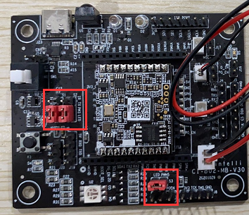
- Connect the control pins of the tricolor lamp with jumper caps at the two red boxes as shown in the figure below.
The jumper cap in the above figure is described as follows:
- Tag No. S1: jumper cap shorting PWM4 and LED;
- Tag No. S2: jumper cap shorting PWM3 and LED;
- Tag No. S3: jumper cap short circuit PWM5 and LED.
After the hardware connection, you can write code to achieve control. SDK is required to write code, as described below:
- The SDK can be downloaded and used in the database of ☞Chipintelli voice AI platform.
For information about software development, please click ☞CI130X chip SDK to learn.
After the firmware development is completed, the firmware needs to be upgraded. Please refer to the following documents for specific operations:
☞Burning and debugging methods
Note: When viewing the document “Burning and Debugging Methods”, pay attention to the following instructions:
- Since the backplane has the function of USB to serial port, the operation can be started from paragraph 2 of 1.1 in the document;
- PG_ The EN pin refers to the red box marked with “10” in the above “Backplane Interface and Application Description” in some documents;
- Select CI110X as the chip model of CI-B02GS01 and CI-B03GS04S; CI-B22GS02S chip model selects CI112X.
You need to further understand the features and usage of the CI-B02GS01, CI-B03GS04S, and CI-B22GS02S voice modules. Please refer to the corresponding module Datasheet
After the module is burned, power on again, confirm that the power on broadcast is normal, can be awakened, and can answer command words and control lights, then the development is completed.
Precautions in application
- The power supply voltage specification of the backplane is 5V ± 5%, and the rated current of the power supply must be greater than 500mA, otherwise the power supply of the voice module may be insufficient when the speaker is working, resulting in abnormal function of the voice module;
- The backplane and voice module shall be stored and operated within the temperature range of 0-85 ℃;
- All communication interfaces of the backplane kit are 3.3V level. When connecting with external equipment, make sure that the communication level of the external equipment is also 3.3V, otherwise it needs to be transferred through the level conversion circuit;
- If you have any questions about the backplane and voice module or have special application/development needs, please consult our technical support personnel.
Frequently Asked Questions
| No. | Problem Phenomenon | Troubleshooting |
|---|---|---|
| 1 | No announcement | 1. Whether the horn is connected to the correct place, refer to the above connection diagram 2. If the power indicator is on, check whether the power supply is normal 5V 3. Whether the power button is in the pop-up state. |
| 2 | No response after saying “智能管家” | 1. Refer to the above connection diagram for whether the microphone is connected to the correct place 2. If the horn is connected to the correct place, refer to the above connection diagram 3. Try to use standard Mandarin 4. Restart and power on to see if it is normal. |
| 3 | The computer cannot recognize the serial port | 1. If the power indicator is on, please check whether the power supply is normal 5V 2. Whether the power button is in the pop-up state 3. Change the direction of one end of the TYPE-C cable connecting the backplane. |
