SDK Quick Start
1. Overview
This document serves as a quick start guide for the CI13XX series chip offline voice software development kit (CI13XX_SDK_ASR_Offline_Vx.x.x), designed to help developers quickly get familiar with the development and debugging process. The SDK can be downloaded at SDK Download Link.
2. User Guide
2.1. Software Development Environment Introduction
2.1.1. Chipintelli Integrated Development Environment
Developers can refer to the “IDE Setup and Usage” guide to set up the Chipintelli integrated development environment. Once set up, the Offline Voice Recognition SDK can be used within this environment.
2.1.2. CI13XX Series Offline Voice Recognition SDK
The SDK includes example projects, technical documentation, and supporting toolkits. Please visit Chipintelli AI Speech Development Platform to download the latest version of the SDK. The SDK includes the firmware packaging tool (PACK_UPDATE_TOOL.exe), which is used for firmware packaging, firmware updates, and debugging of the CI13XX series chips. For operation steps, please refer to the “Firmaware Update” document.
2.2. Hardware Development Board Introduction
The following uses the CI1306 Development Board Kit as an example to introduce the hardware. This development board can be purchased at Purchase Link. For usage of other development boards, please refer to their respective user guides.
| Development Board Kit | Supported Chips | Purchase Link | User Guide |
|---|---|---|---|
| CI1306 Development Board Kit | CI1306 | Purchase | User Guide |
| CI1303 Development Board Kit | CI1303, CI1302, CI1301 | Purchase | User Guide |
| CI1302 Development Board Kit | CI1302, CI1301 | Purchase | User Guide |
2.2.1. Development Board Physical Diagram
Development Board Model: CI-D06GT01D (Chip Model: CI1306).

2.2.2. Main Interfaces of the Development Board
- The main interfaces of the CI-D06GT01D development board are shown in the figure below.
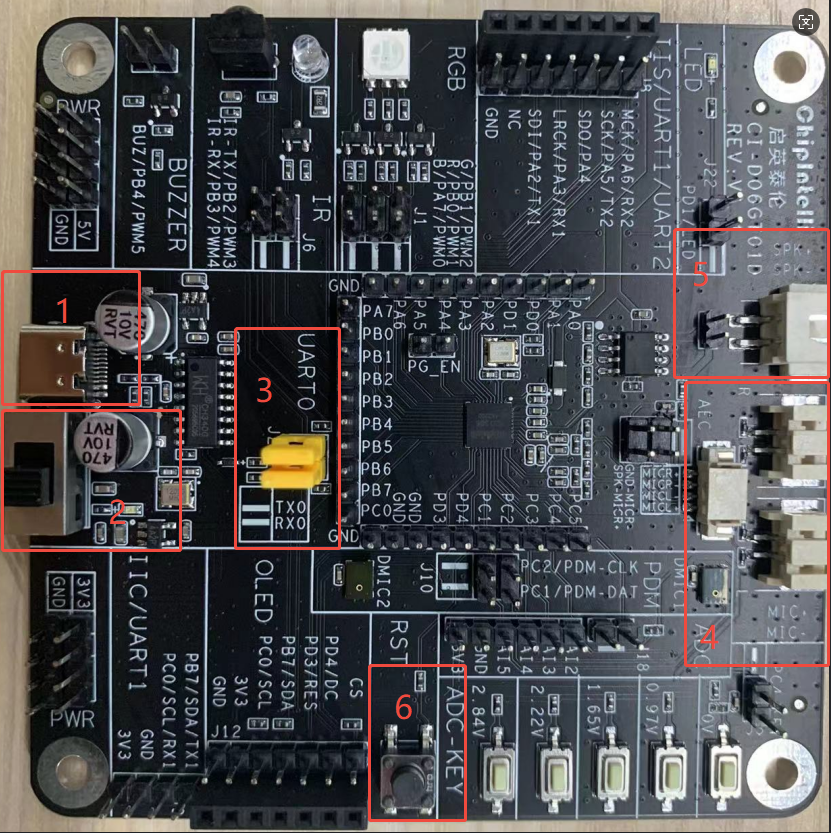
- 1: USB Type-C Interface - Provides 5V power supply and supports firmware update and debugging;
- 2: USB Type-C 5V Power Supply DIP Switch;
- 3: UART0 TX/RX Pins - Used for firmware update and debugging. If using USB Type-C for firmware update and debugging, short these pins vertically;
- 4: Microphone Base;
- 5: Speaker Base;
- 6: Reset Button, which needs to be pressed during the firmware update process to start the upgrade.
3. Application Development
For developing applications for the CI13XX series chips, we provide an offline voice recognition SDK (CI13XX_SDK_ASR_Offline_Vx.x.x) for code development. The following sections will introduce this SDK.
3.1. SDK Architecture Overview
| File/Directory | Description |
|---|---|
| components | Components: Player, ASR Recognition, Buttons, Sensors, FreeRTOS, etc. |
| driver | CI13XX series chip drivers, board support configuration |
| libs | Precompiled static/dynamic library files |
| projects | Example projects |
| startup | CI13XX series chip startup code |
| system | System-related code, interrupt handlers, platform configuration |
| tools | Tools: images synthesis, firmware pack and updatetool |
3.2. CI13XX_SDK_ASR_Offline_Vx.x.x Example Projects
For quick start, CI13XX_SDK_ASR_Offline_Vx.x.x comes with multiple example projects. By compiling and running these examples, developers can quickly understand the architecture and usage of the SDK.
Example Project Path: CI13XX_SDK_ASR_Offline_Vx.x.x\projects\
| Project File | Description |
|---|---|
| offline_asr_pro_sample | Offline Voice Recognition Pro Version Example Project |
4. Firmware Update
4.1 *.bin File Description
CI13XX application firmware consists of 5 bin files:
| Image File | Description |
|---|---|
asr.bin |
Language Model |
dnn.bin |
Acoustic Model |
user_code.bin |
Application, compiled and generated by the SDK |
user_file.bin |
Developer-defined command word list and other bin files |
voice.bin |
Voice Prompts |
4.2 *.bin File Generation Script
- Path:
CI13XX_SDK_ASR_Offline_Vx.x.x\projects\offline_asr_pro_sample\firmware\ - Script:
make_partition_bin.bat - Function: After execution, the system will automatically generate four partition files
asr.bin,dnn.bin,user_file.bin, andvoice.binin thefirmware\\asr,dnn,user_file, andvoicesubdirectories.
4.3 Firmware Pack and Update
The following uses the offline_asr_pro_sample project as an example to explain how to use the serial port programming tool PACK_UPDATE_TOOL.exe to complete the firmware update.
Step 1: Hardware Connection
The development board provides two common firmware update connection methods. Choose the appropriate method based on your actual environment:
- USB Type-C Direct Connection - Uses the onboard USB-to-serial controller, allowing power supply, serial communication, and firmware update with a single cable;
- USB-to-TTL - When a USB Type-C cable is not available, use a USB-to-TTL Tool for power supply and connect the chip’s TX/RX pins to the adapter’s RXD/TXD pins for firmware update.
Method A: USB Type-C Direct Connection

- 1: USB Type-C cable, connected to PC, refer to label 1 in the figure above
- 2: Connect UART0_TX to UART0_RX, refer to label 2 in the figure above
Method B: Firmware Update Using USB-to-TTL
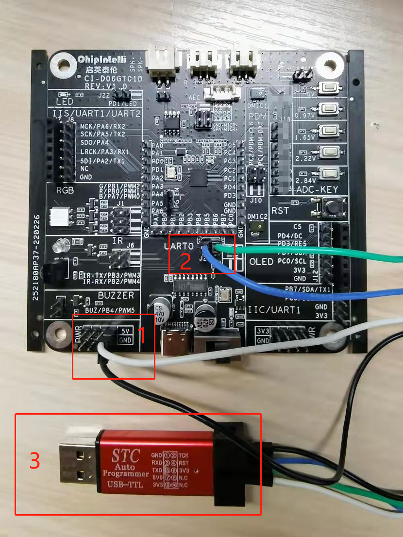
- 1: 5V Power Supply (VCC/GND), refer to label 1 in the figure above
- 2: UART0_TX → Adapter RXD, UART0_RX → Adapter TXD, refer to label 2 in the figure above
- 3: USB-to-TTL - Connect to PC via USB port
Step 2: Compile and Generate user_code.bin
-
Refer to the “IDE Setup and Usage” document to complete the environment configuration and execute the compilation by first click
cleanand then clickbuild. -
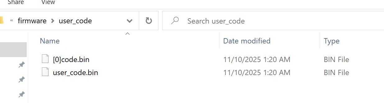
After compilation,
user_code.binwill be generated in theprojects\offline_asr_pro_sample\firmware\user_codedirectory (see Figure 4-3).
Step 3: Generate the Remaining Four bin Files
Two methods are provided:
Method 1: Generate Directly in VSCode
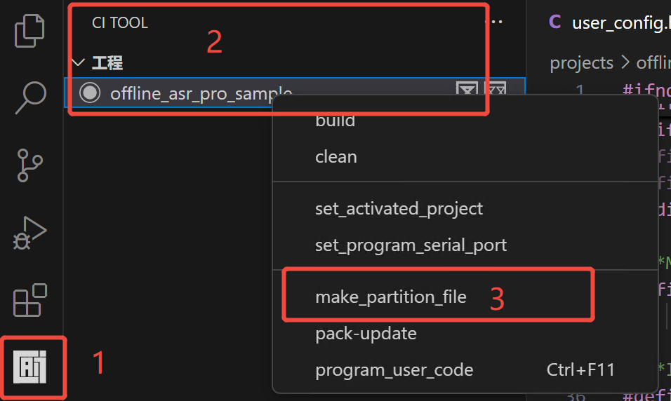
- Run
make_partition_bin.batin VSCode (see Figure 4-4).
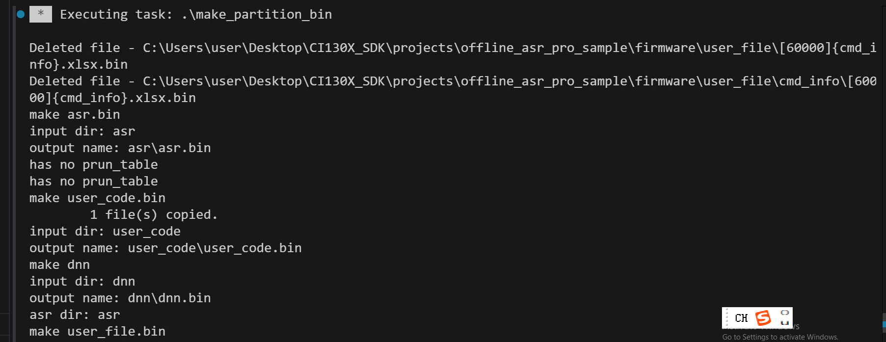
- The running result displayed in the VSCode terminal is shown in Figure 4-5.
Method 2: Double-Click the Batch Script
- Navigate to the
projects\offline_asr_pro_sample\firmwaredirectory (Figure 4-6).
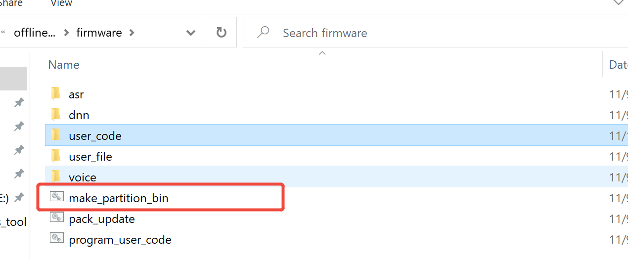
- Double-click
make_partition_bin.bat. After the script starts running, the interface shown in Figure 4-7 will appear. After the script completes, the corresponding bin files will be automatically generated in theasr,dnn,user_file, andvoicesubdirectories.
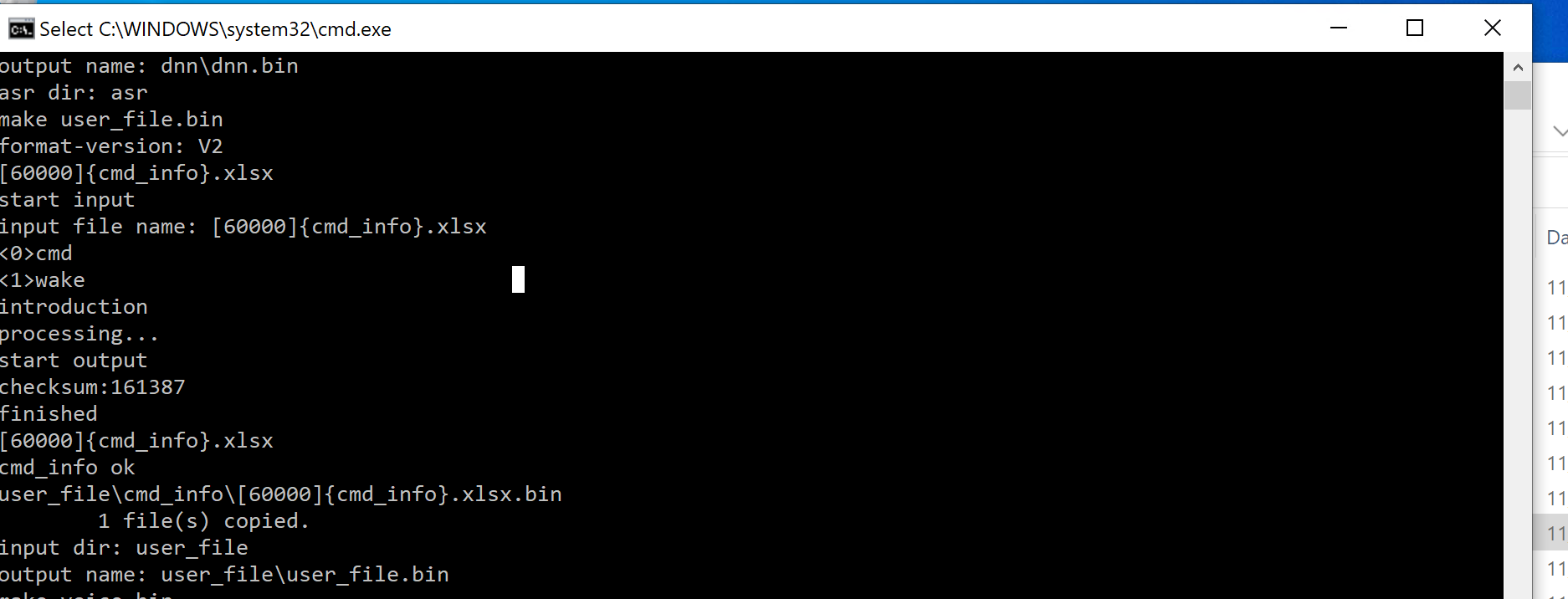
Note
After processing, cmd.exe will exit automatically. If it does not exit automatically, the *.bin file generation has failed. Please check the files or filenames in the asr, dnn, user_file, and voice directories.
Step 4: Merge the Five bin Files
There are two ways to launch PACK_UPDATE_TOOL.exe (choose one):
Method 1: Launch in VSCode
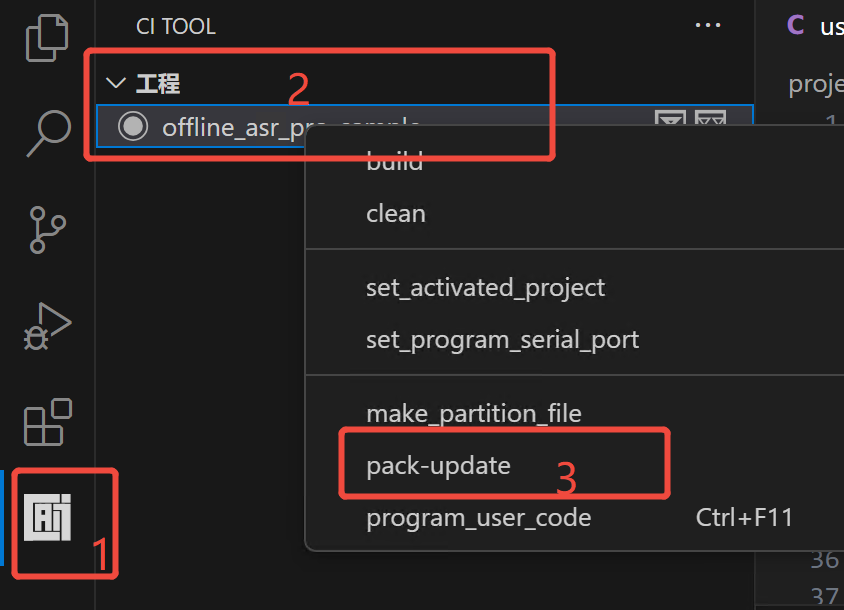
- Launch the pack and updatetool
PACK_UPDATE_TOOL.exein VSCode (see Figure 4-8).
Method 2: Double-Click the Batch Script
- Navigate to the
projects\offline_asr_pro_sample\firmwaredirectory, as shown in Figure 4-6. - Double-click
Pack_update.bat, and the script will automatically callPACK_UPDATE_TOOL.exe.
When launching PACK_UPDATE_TOOL.exe for the first time, a chip series selection dialog will pop up (Figure 4-10). Please select “CI13XX Series” and “CI1306” chip to continue.
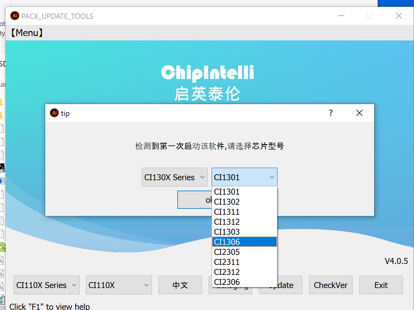
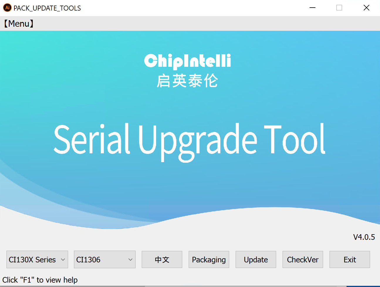
Serial Upgrade Tool Main Interface Introduction:
- CI130X Series Chips - Current mode is for CI130X series chips
- CI1306 - Currently selected chip model is CI1306
- English - Switch interface language (Chinese/English)
- Firmware Package - Enter the firmware packaging interface
- Firmware Update - Enter the firmware update interface
- F1 - Open help documentation
Click the (Firmware Package) button on the main interface of the serial upgrade tool, and the interface will be as shown in Figure 4-12:
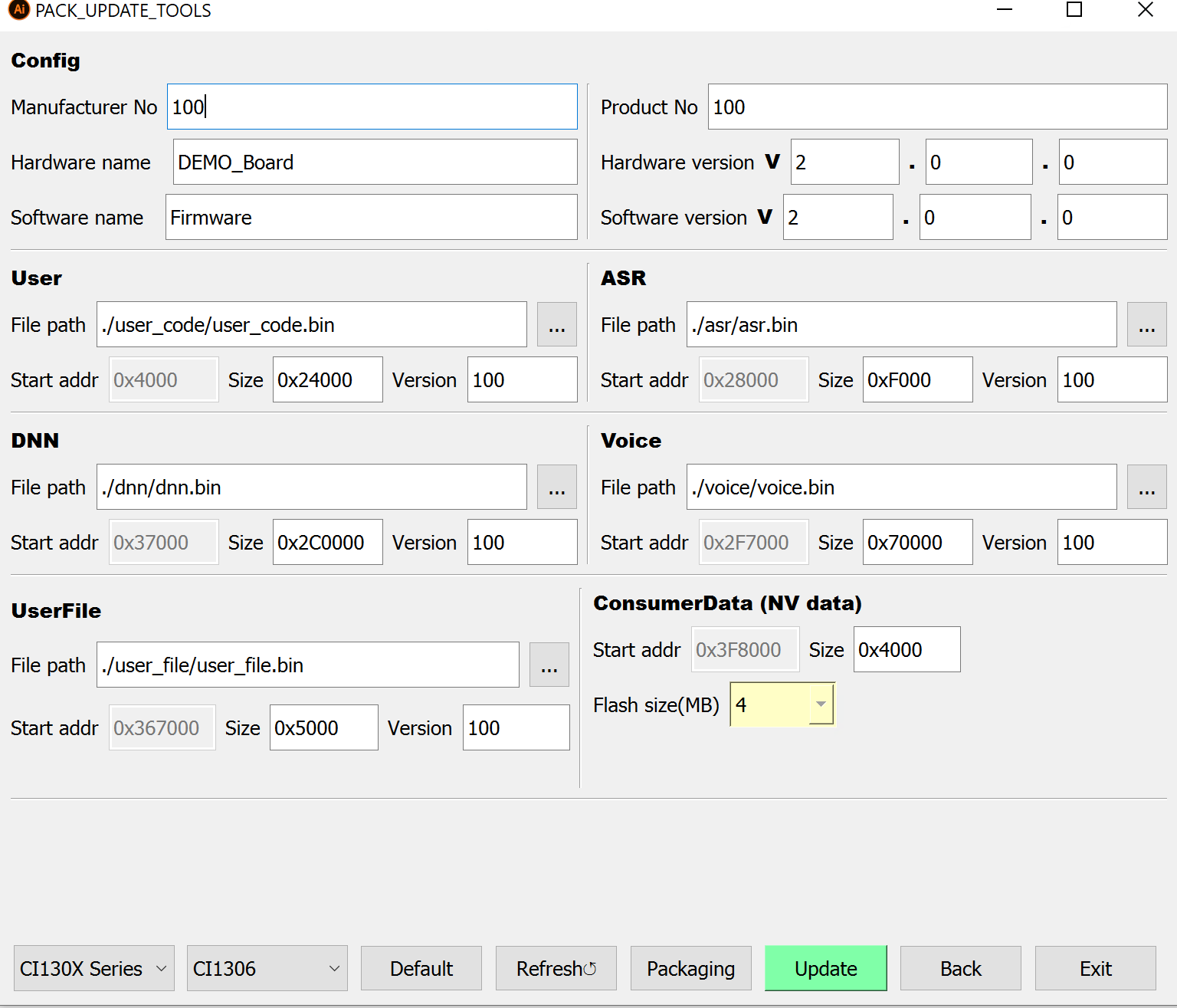
Check and adjust the “Reserved Size” of the five partitions according to the actual size of each bin file. Example:
- If the actual size of user_code.bin is 0x232A3 bytes and the original reserved size is 0x23000, it should be changed to ≥ 0x24000
- If the actual size of voice.bin is 0xD80B9 bytes and the original reserved size is 0xF0000, it should be reduced to a value close to but not less than the actual size, such as 0xD9000, to avoid wasting Flash space.
Note: The reserved size must be in increments of 0x1000.
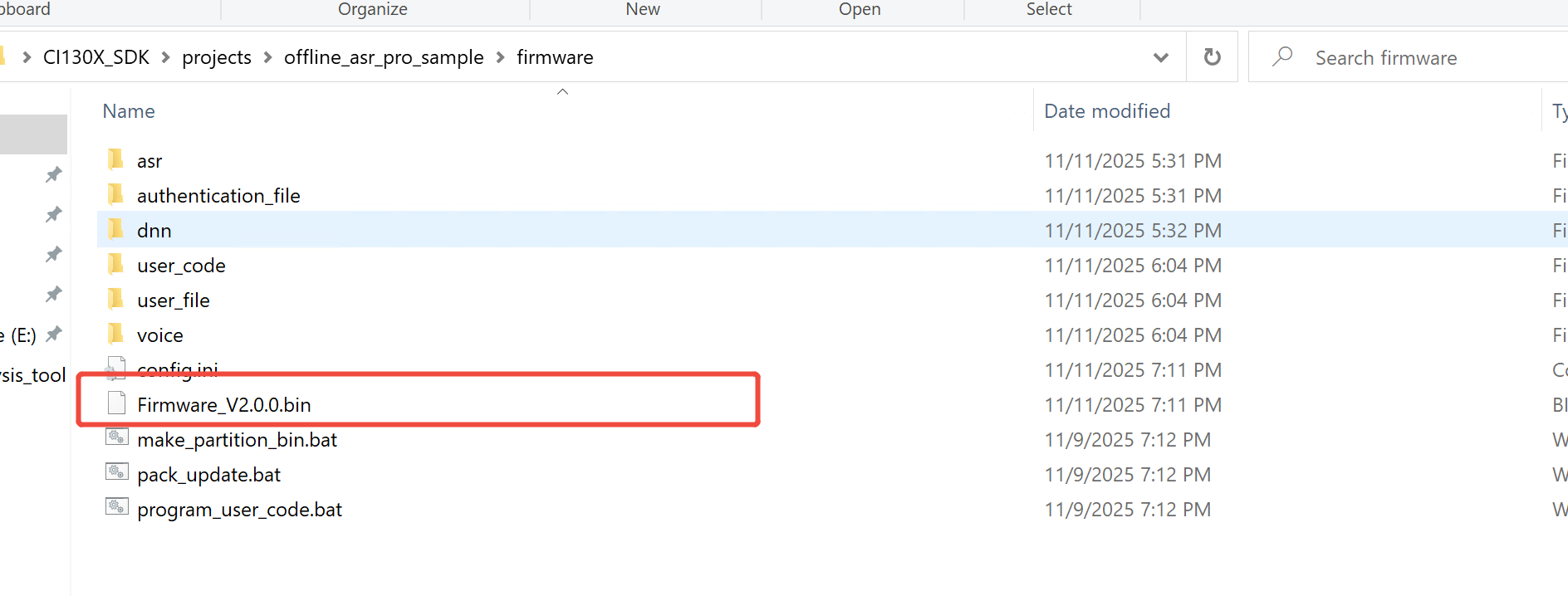
After clicking the “Packaging” button, a “Firmware Generated Successfully” dialog will appear. Click “OK” to complete the firmware generation. The firmware will be saved in the projects\\offline_asr_pro_sample\\firmware directory, with the filename automatically generated by combining the software name and version number, such as Firmware_V200.bin (Figure 4-13).
Step 5: Update Firmware
Before upgrading, please confirm the following:
- Ensure the hardware connections are correct (refer to Step 1);
- Confirm that the USB Type-C cable or USB-to-TTL Tool is connected to the PC, and the corresponding COM port is recognized;
- Verify that the firmware has been successfully generated;
- Ensure the microphone and speaker are properly connected to the development board.
Click the firmware update button in Figure 4-10 or 4-11 to see the interface shown in Figure 4-14:
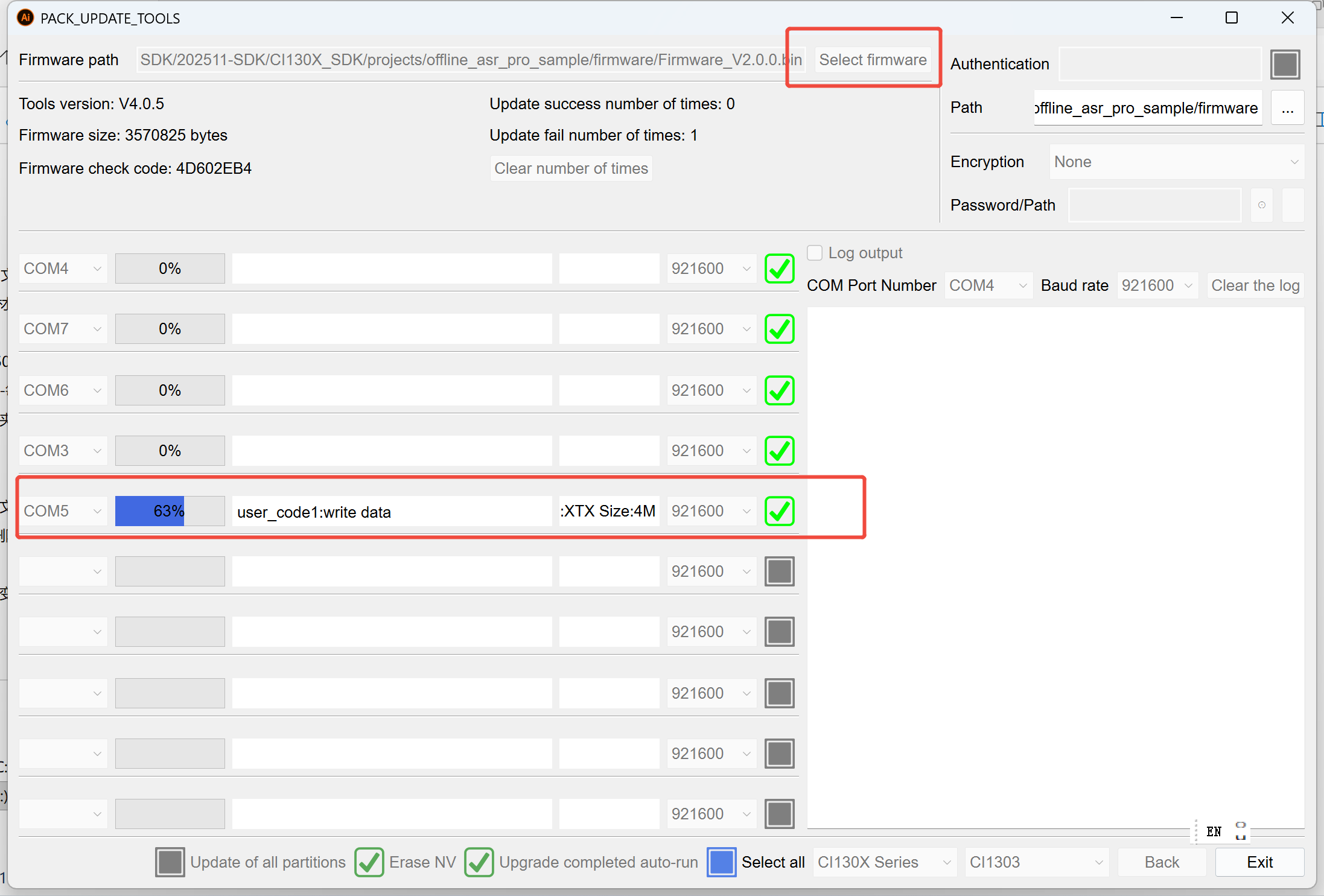
- Select the firmware file generated in Step 4, or use the official Chipintelli firmware;
- Select the correct COM port;
- Reset the development board (press the reset button or power cycle, as shown in Figure 2-3), and the upgrade tool will start the upgrade automatically; the status bar will display
Update successfulwhen completed.
Tip: For more information on firmware creation, please refer to Command Words and Firmware Creation Guide, or press F1 on the home page shown in Figure 4-10 for help.
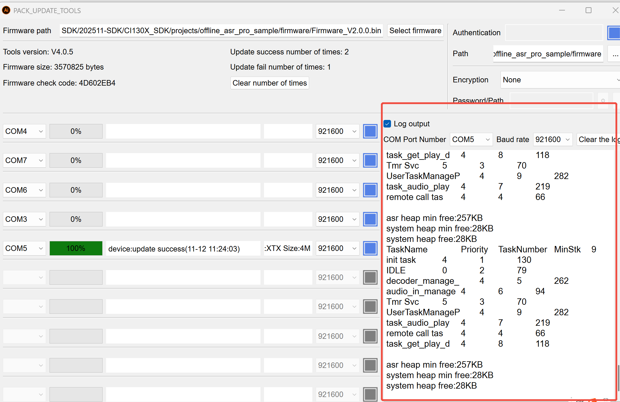
Step 6: Verify Firmware
After the firmware update is complete, power cycle the development board or press the reset button. The offline_asr_pro_sample project will play a startup tone. After the tone, say the wake word “Hello Jenny” to receive a response with “Hello”, indicating a successful upgrade. To change command words/prompts, please refer to Voice Firmware Development Guide
Tip: If you don’t hear any voice prompts, please refer to Chapter 5 “Debugging” for troubleshooting.
5. SDK Debugging
The SDK includes a Log-based debugging mechanism to track code execution flow and key data.
5.1. Log Mechanism
Developers can output Log information through the serial port to track application runtime status.
5.1.1. Log Output Pin Configuration
By default, UART0_TX is the output pin for the Log serial port. To use a different serial port, configure the macro CONFIG_CI_LOG_UART in user_config.h (Figure 5-1).
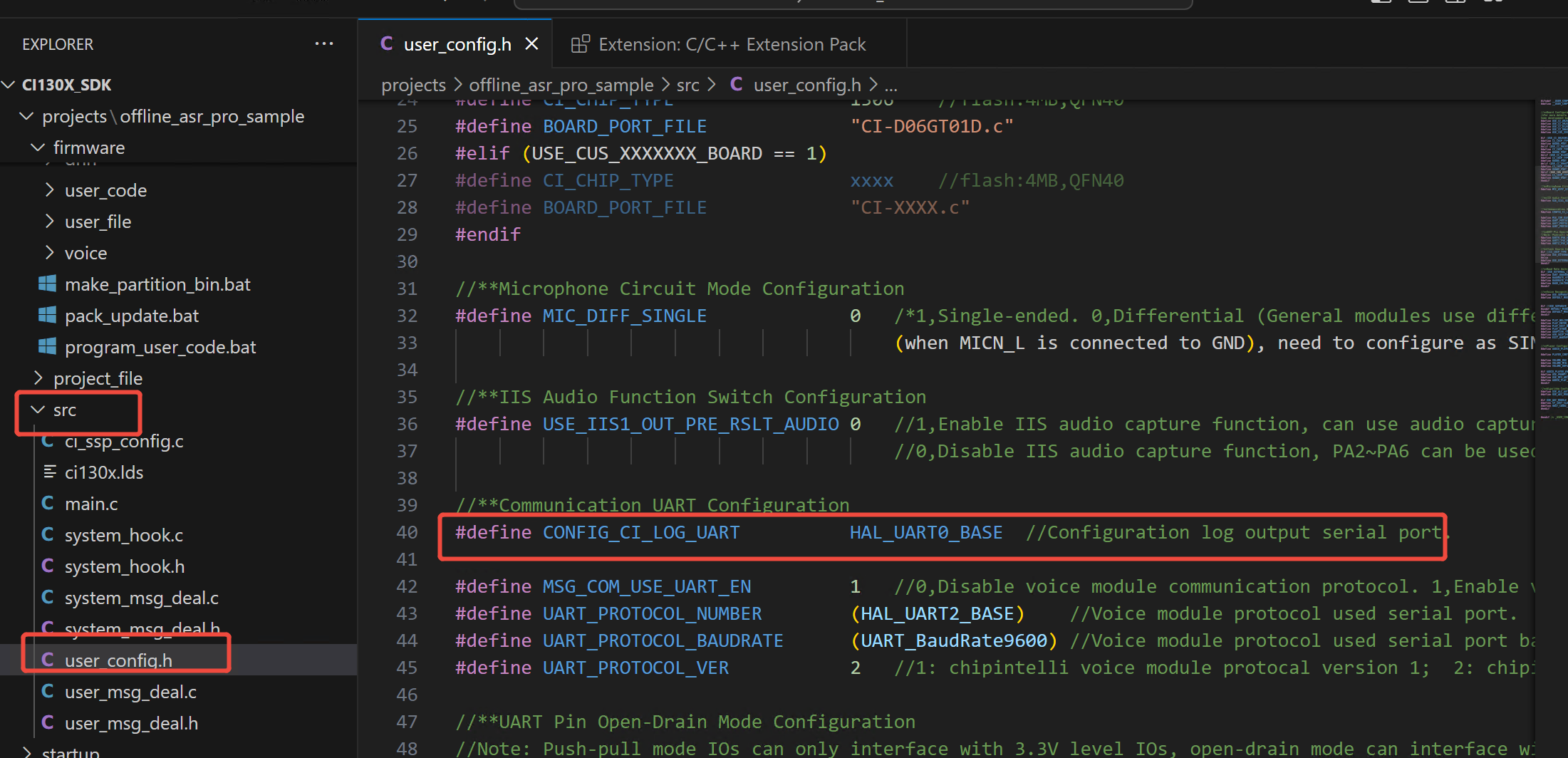
It is recommended to modify the configuration only in user_config.h within the project path, avoiding direct modifications to sdk_default_config.h.
5.1.2. Serial Debug Tool Configuration for Logging
Below is an example of PC serial debug tool configuration. Select the COM port assigned by the system to the USB-to-TTL Tool, with the baud rate set to 921600:
Note: The serial port output contains Chinese characters; please use a serial debug tool that supports UTF-8 fonts.
Professional serial debug tools such as SecureCRT are recommended.
5.1.3. General Log Printing Interface
General Log printing interface:
mprintf(fmt, args...); // Usage is the same as printf
5.1.4. Log Printing API
For user convenience in debugging, the SDK provides the following interfaces:
Table 5-1 Printing APIs
| Debug API | Function |
|---|---|
| ci_logverbose(comlevel, message, args…) | Verbose log printing |
| ci_logdebug(comlevel, message, args…) | Debug log printing |
| ci_loginfo(comlevel, message, args…) | Info log printing |
| ci_logwarn(comlevel, message, args…) | Warning log printing |
| ci_logerr(comlevel, message, args…) | Error log printing |
| ci_logassert(comlevel, message, args…) | Assertion log printing |
Debug levels define the verbosity of log output. Seven levels are defined:
Table 5-2 Debug Levels
| Debug Level | Usage Scenario |
|---|---|
| #define CI_LOG_VERBOSE | Print all messages |
| #define CI_LOG_DEBUG | Debug, info, warning, error, assert |
| #define CI_LOG_INFO | Info, warning, error, assert |
| #define CI_LOG_WARN | Warning, error, assert |
| #define CI_LOG_ERROR | Error, assert |
| #define CI_LOG_ASSERT | Assert only |
| #define CI_LOG_NONE | No output |
Note: To use the APIs shown in Table 5-1, set
CONFIG_CI_LOG_ENto 1 in the configuration.
5.1.5. Log Print Length Configuration
#define UART_LOG_BUFF_SIZE 512
The default print length is 512 bytes, which can be adjusted using the UART_LOG_BUFF_SIZE macro.
6. Conclusion and Support
You have now completed the environment setup, firmware update, and basic debugging process for the CI13XX series SDK. Based on your business needs, you can proceed with secondary development on the example projects or quickly integrate more features by referring to the component source code.