Product Structural Design
Microphone Structural Design
Speech and Propagation Characteristics
- Vibration Concept: In physics, vibration is broadly defined as any physical process that repeats periodically over time. Simply put, the back-and-forth motion of particles or objects is called “vibration,” which is a method of energy propagation.
- Sound Generation: When one or more particles vibrate, they cause surrounding particles to vibrate as well. During this process (object vibration), energy waves are produced in the air (including infra-sound, sound waves, and ultrasound). Vibrational waves that can be detected by human hearing are called sound waves, with a frequency range of approximately 20-20,000 Hz.
- Speech is the transmission of human language through sound waves. Language + sound waves = speech. Speech recognition involves decoding and recovering language from speech.

Microphone Selection Recommendations
- Choose analog microphones with a sensitivity of -32±3dB and signal-to-noise ratio >70dB. Refer to ☞Microphone Compatibility List for compatible models.
- Select single-microphone or dual-microphone solutions based on functionality. Contact our technical team for specific recommendations.
- Common microphone sizes are 7mm or 10mm rubber gaskets. Use 7mm for standard applications; opt for 10mm if vibration is present. Select interface type, cable length, and other specifications based on requirements.
Microphone Inlet Design Recommendations
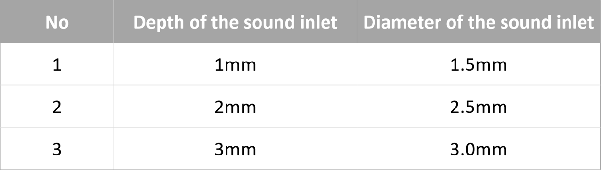
- Inlet Design: A sound inlet hole is mandatory. The diameter should correlate with the hole depth (housing thickness). See recommended specifications below:
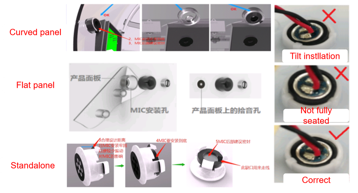
- Position the microphone hole on the front of the product, facing the user, to ensure optimal sound pickup and avoid obstruction by other components.
- Consider waterproofing and dust-proofing for the microphone location if exposed to water or dust.
- Keep away from water inlets, air vents, machinery, speakers, electromagnetic interference, and other noise sources. For best recognition performance, ensure ambient noise at the microphone remains below 60dB during operation.
- Include mounting holes or slots that match the rubber gasket diameter (7mm or 10mm). Confirm exact dimensions with the microphone manufacturer, typically 0.1-0.2mm smaller than the microphone diameter.
- Ensure convenient cable routing, away from high-voltage lines.
- For dual-microphone setups, maintain a 4cm center-to-center distance. Consult our FAE for other spacing requirements.
- For AEC (Acoustic Echo Cancellation) functionality, maximize distance between microphones and speakers. Keep speaker output below 95dB and microphone input below 83dB.
- Consult our technical team before finalizing the structural design.
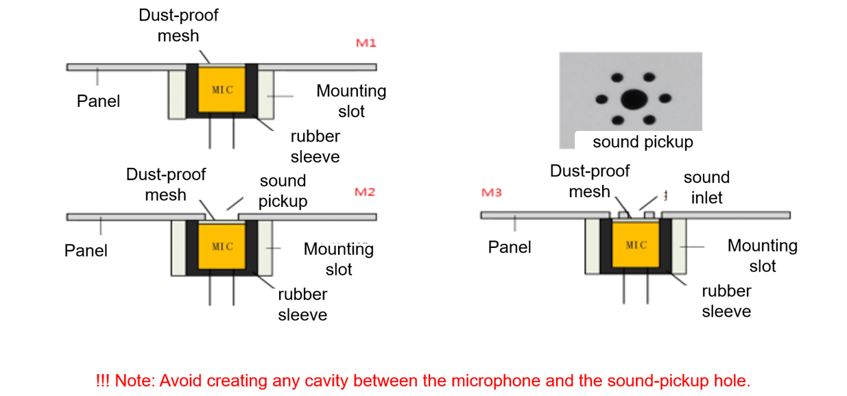
- Avoid cavities between the sound inlet and microphone. Consider using a honeycomb pattern if needed.
Microphone Installation Guidelines
- Secure the microphone firmly to prevent movement, which could affect recognition.
- Use RoHS-compliant RTV silicone (e.g., 703/704/737) or other organic materials.
- Choose non-conductive silicone to prevent electrostatic discharge (ESD) from reaching the microphone pins. Contact the microphone manufacturer or our FAE for suitable adhesive types.
- Insert the microphone fully into the mounting hole, ensuring proper alignment with the sound inlet.
- Apply silicone with a thickness under 3mm. Allow 8-12 hours for full curing at room temperature. For thicker applications, apply in layers. Complete microphone installation early in production.
- Avoid using hot glue for microphone fixation. Secure the wiring to prevent misalignment during handling.