Chipintelli AI Voice Serial Port Debugging Tool User Manual
Serial Port Debugging Tool
A serial port debugging tool is primarily used for serial communication between a computer and external devices (such as voice development boards). It can convert computer data into serial signals for transmission to external devices, or convert serial signals from external devices into computer-readable data. Serial port debugging tools are commonly used in embedded system development, hardware debugging, and device control. Purchase link: ☞Serial Port Debugging Tool.

How to Use the Serial Port Debugging Tool
-
Install Serial Port Drivers: First, install the drivers that match your serial port debugging tool on your computer to ensure proper recognition and communication with the serial port device. For the widely used CH340 USB-to-Serial chip, you can search for “CH340 official driver” in your browser, visit the official website, and download the appropriate driver for your operating system. Download link: ☞CH340 Official Driver.
-
Open Serial Port Debugging Assistant: After installation, open the serial port debugging assistant software. In the software interface, select the correct parameters such as COM port, baud rate, data bits, stop bits, and parity to ensure they match the communication settings of your serial port device. For software download, refer to: ☞SSCOM 5.13.1 Download. For quick start, refer to: ☞SSCOM5.13.1 Usage.
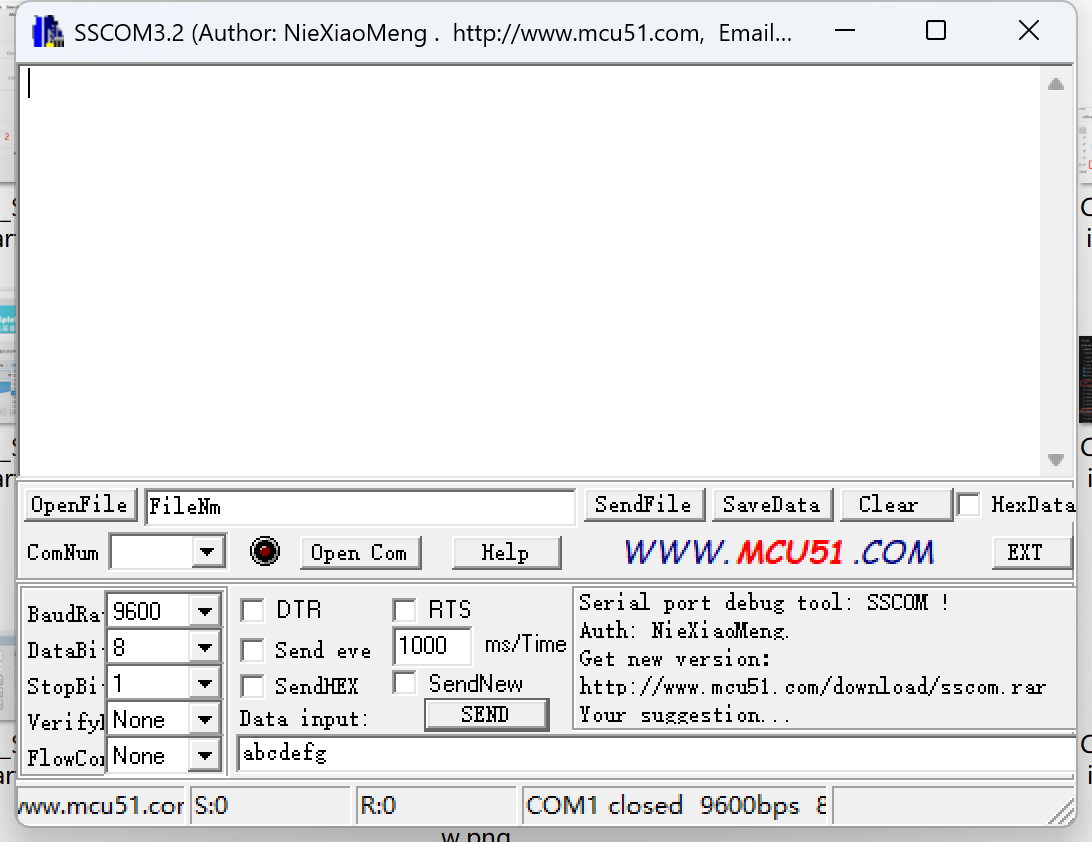
- Send and Receive Data: After configuring the parameters, you can send data to external devices or receive data from them. To send data, enter the content in the send box of the serial port debugging assistant and click the
sendbutton. For receiving data, the assistant will automatically display the received data in the receive box.
TX and RX Connection Requirements
In serial communication, TX stands for Transmit and RX stands for Receive. Generally, the TX pin of the computer’s serial port should be connected to the RX pin of the external device, and the RX pin of the computer’s serial port should be connected to the TX pin of the external device. This allows the computer to send data to and receive data from the external device via the serial port.
Features for Chipintelli AI Voice Chips (Hereafter Referred to as CI Chips)
-
Firmware Programming: CI chips typically require a serial port debugging tool for firmware programming. During the programming process, the CI chip needs to be connected to the computer’s serial port, and the firmware file will be write to CI chips through the serial port debugging tool. After successful programming, the CI chip can function according to the predefined program. For detailed instructions with images, refer to: ☞SDK Quick Development.
-
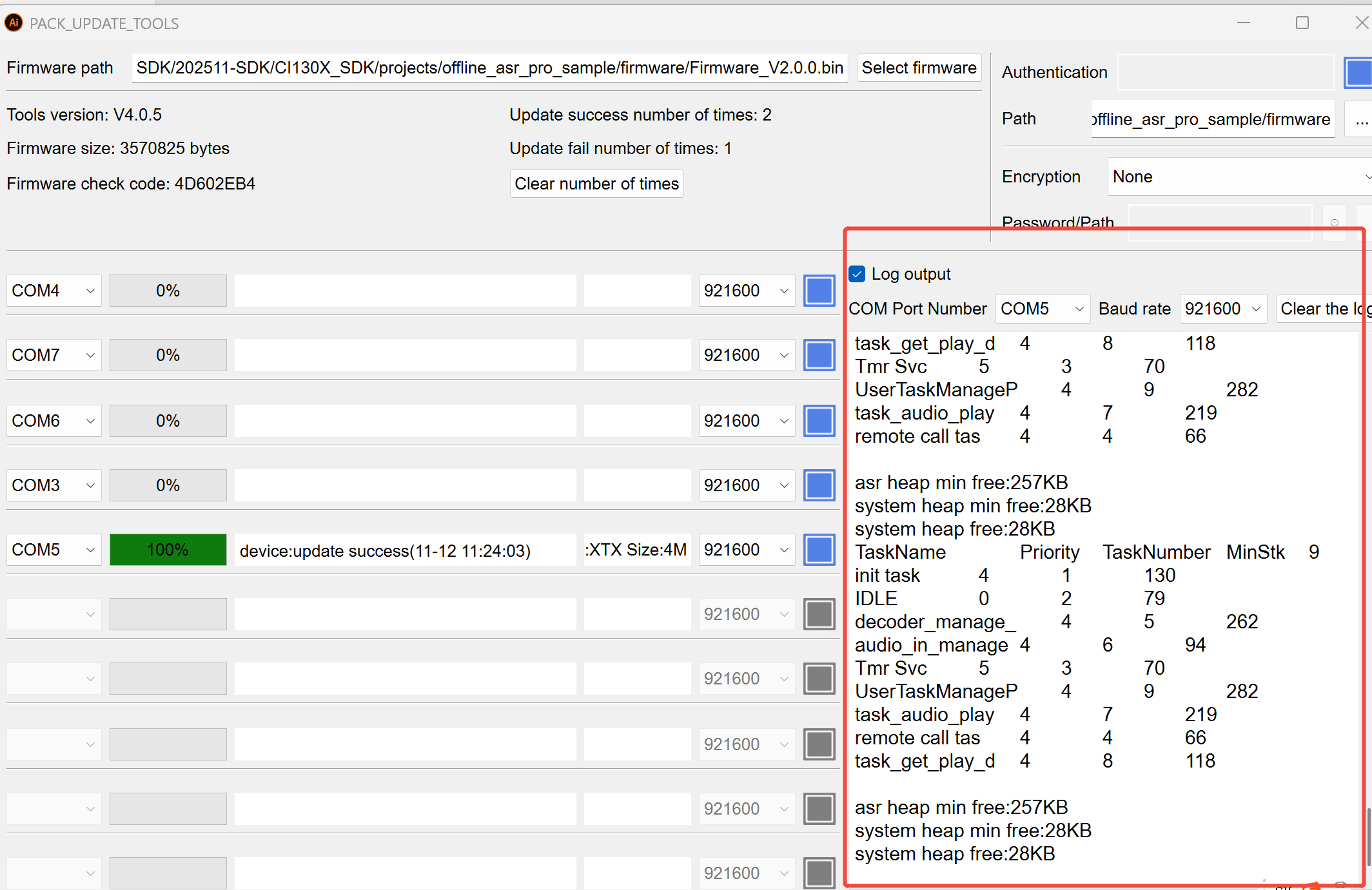
Reading Logs: By default, CI chip programs can print logs through
COM0used for programming, making it convenient for developers to debug. Thepack_update_toolalso includes a log viewing feature in the upgrade interface. Select the corresponding COM port (default baud rate is 921600) and check the box before log output to view the runtime logs.
- Serial Port Audio Analysis: CI chips can also perform audio analysis through the serial port debugging tool. During audio capture, the tool can send the audio signals collected by the CI chip to the computer for processing and analysis. This helps evaluate the audio capture performance and sound quality of the CI chip. For detailed instructions with images, refer to: ☞Chipintelli Audio Acquisition Board Operation Manual and Voice Module Board Noise Analysis_V1.3.
Purpose of USB Isolator
A USB isolator is a device used to protect computers and external devices from electrical interference and damage. It isolates the electrical connection between the computer and external devices, preventing electrical noise and interference from affecting communication and data. When purchasing and using an isolator, select a model and specifications that match your computer and external devices, and follow the instructions for proper connection and configuration. Purchase link: ☞USB Isolator Purchase Link
Note
This tool is only needed when the circuit board is powered by a non-isolated power supply. It is not required when using an isolated power supply.
Additional Notes
-
When using the serial port debugging tool, ensure stable and reliable electrical connections between the computer and external devices to avoid communication failures or data loss due to poor contact or loose connections.
-
When configuring serial port parameters, ensure they are set correctly according to the actual serial port device and communication protocol to ensure proper communication.
-
When performing firmware programming or audio analysis, follow the operation steps and precautions in the relevant tutorials or documentation to avoid damage to the CI chip or computer, or data loss.
-
When using an isolator, select the appropriate model and specifications, and follow the instructions for proper connection and configuration to ensure optimal isolation and protection.