Pulse Width Modulation (PWM)
1. Introduction
- PWM is a technique that approximates analog signal levels by adjusting the duty cycle of a digital pulse (the proportion of time the signal is high within a cycle). It is widely used in motor control, power management, LED dimming, etc.
- CI13XX supports 6 dedicated PWM outputs: PWM0~PWM5.
- The output frequency is configured via
pwm_init. The duty cycle is configured viapwm_init/pwm_set_duty. 100% duty (always high) is not supported; if 100% is required, use GPIO configuration instead.
2. Features
- Counter clock prescaler supports ÷½/4/16 via
pwm_init. - Two 32‑bit decrementing counters.
- Variable duty‑cycle PWM waveform output.
3. API List
| Function | Description |
|---|---|
| pwm_init | Initialize PWM device |
| pwm_start | Start PWM device |
| pwm_stop | Stop PWM device |
| pwm_set_duty | Set PWM duty cycle |
| pwm_set_restart_md | Select counter restart effect mode |
4. General I/O Examples
(1) Configure and start PWM5 at 1 kHz with 50% duty cycle
#include "ci130x_scu.h"
#include "ci130x_dpmu.h"
#include "ci130x_pwm.h"

void pwm_test()
{
    /* PWM5 controller clock configuration */
    scu_set_device_gate(HAL_PWM5_BASE,ENABLE);

    /* PWM5 pin initialization */
    dpmu_set_io_reuse(PB4,SECOND_FUNCTION);              // Set pin function reuse
    dpmu_set_io_direction(PB4,DPMU_IO_DIRECTION_OUTPUT); // Configure pin as output
    dpmu_set_io_pull(PB4,DPMU_IO_PULL_DISABLE);          // Disable internal pull-up/down

    /* Initialize PWM5 frequency and duty */
    pwm_init_t init;
    init.clk_sel = 0;    // Counter clock sourced from PCLK
    init.freq = 1000;    // Frequency 1 kHz
    init.duty = 50;      // Numerator for 50% duty
    init.duty_max = 100; // Denominator for 50% duty
    pwm_init(PWM5,init);

    /* Start PWM5 */
    pwm_stop(PWM5);      // PWM off
    pwm_start(PWM5);     // PWM on
}
(2) The IP adds a selectable “restart count effect” mode. After initialization, when switching duty cycles, you may want the previous PWM waveform to complete before the new duty takes effect upon a counter restart. See example below.
#include "ci130x_scu.h"
#include "ci130x_dpmu.h"
#include "ci130x_pwm.h"

void pwm_test()
{
    /* PWM5 controller clock configuration */
    scu_set_device_gate(HAL_PWM5_BASE,ENABLE);

    /* PWM5 pin initialization */
    dpmu_set_io_reuse(PB4,SECOND_FUNCTION);              // Set pin function reuse
    dpmu_set_io_direction(PB4,DPMU_IO_DIRECTION_OUTPUT); // Configure pin as output
    dpmu_set_io_pull(PB4,DPMU_IO_PULL_DISABLE);          // Disable internal pull-up/down

    /* Initialize PWM5 frequency and duty */
    pwm_init_t init;
    init.clk_sel = 0;      // Counter clock sourced from PCLK
    init.freq = 1000;      // Frequency 1 kHz
    init.duty = 50;        // Numerator for 50% duty
    init.duty_max = 100;   // Denominator for 50% duty
    pwm_init(PWM5,init);
    pwm_set_restart_md(PWM5,1);   // New duty takes effect after current PWM waveform completes and counter restarts

    /* Start PWM5 */
    pwm_stop(PWM5);        // PWM off
    pwm_start(PWM5);       // PWM on

    /* Mid-run duty switch for PWM5 */
    pwm_set_duty(PWM5,30,100)    // Switch to 30% duty
}
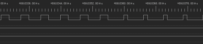
When configured to take effect after the ongoing PWM waveform completes and the counter restarts, the waveform is as follows:
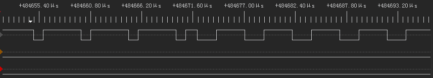
When configured to take effect immediately without waiting (pwm_set_restart_md(PWM0,0)), the waveform is as follows:
(3) Complementary output using two PWM groups
#include "ci130x_scu.h"
#include "ci130x_dpmu.h"
#include "ci130x_pwm.h"
#include "task.h"

void pwm_test()
{
    /* PWM5 controller clock configuration */
    scu_set_device_gate(HAL_PWM5_BASE,ENABLE);

    /* PWM5 pin initialization */
    dpmu_set_io_reuse(PB4,SECOND_FUNCTION);              // Set pin function reuse
    dpmu_set_io_direction(PB4,DPMU_IO_DIRECTION_OUTPUT); // Configure pin as output
    dpmu_set_io_pull(PB4,DPMU_IO_PULL_DISABLE);          // Disable internal pull-up/down

    /* Initialize PWM5 frequency and duty */
    pwm_init_t init;
    init.clk_sel = 0;     // Counter clock sourced from PCLK
    init.freq = 16000;    // Frequency 1.6 kHz
    init.duty = 50;       // Numerator for 50% duty
    init.duty_max = 100;  // Denominator for 50% duty
    pwm_init(PWM5,init);
    pwm_stop(PWM5);       // PWM off

    /* PWM0 controller clock configuration */
    scu_set_device_gate(HAL_PC_BASE,ENABLE);

    /* PWM0 pin initialization */
    scu_set_device_gate(HAL_PWM0_BASE,ENABLE);
    dpmu_set_io_reuse(PC4,FORTH_FUNCTION);              // Set pin function reuse
    dpmu_set_io_direction(PC4,DPMU_IO_DIRECTION_OUTPUT); // Configure pin as output
    dpmu_set_io_pull(PC4,DPMU_IO_PULL_DISABLE);          // Disable internal pull-up/down

    /* Initialize PWM0 frequency and duty */
    init.clk_sel = 0;    // Counter clock sourced from PCLK
    init.freq = 16000;   // Frequency 1.6 kHz
    init.duty = 50;      // Numerator for 50% duty
    init.duty_max = 100; // Denominator for 50% duty
    pwm_init(PWM0,init);
    pwm_stop(PWM0);      // PWM off

    /* Start PWM0 and PWM5 with an offset to achieve complementary output */
    {
        volatile uint32_t i = 0;
        taskENTER_CRITICAL();
        pwm_start(PWM5);
        for (i = 0;i < 0x210;i++);
        pwm_start(PWM0);
        taskEXIT_CRITICAL();
    }
}
5. Crystal Oscillator I/O Example
(1) PA0 connects to the crystal oscillator and is analog by default. The following configures PA0 reused as PWM5, 1 kHz, 50% duty cycle.
#include "ci130x_scu.h"
#include "ci130x_dpmu.h"
#include "ci130x_pwm.h"

void pwm_test()
{
    /* Enable crystal pads for GPIO usage */
    dpmu_osc_pad_for_gpio(ENABLE);                       // To use PA0 as PWM, the oscillator must be disabled

    /* PWM5 controller clock configuration */
    scu_set_device_gate(HAL_PWM5_BASE,ENABLE);

    /* PWM5 pin initialization */
    dpmu_set_io_reuse(PA0,SECOND_FUNCTION);              // Set pin function reuse
    dpmu_set_adio_reuse(PA0,DIGITAL_MODE);               // Set to digital mode; default is analog
    dpmu_set_io_direction(PA0,DPMU_IO_DIRECTION_OUTPUT); // Configure pin as output
    dpmu_set_io_pull(PA0,DPMU_IO_PULL_DISABLE);          // Disable internal pull-up/down

    /* Initialize PWM5 frequency and duty */
    pwm_init_t init;
    init.clk_sel = 0;     // Counter clock sourced from PCLK
    init.freq = 1000;     // Frequency 1 kHz
    init.duty = 50;       // Numerator for 50% duty
    init.duty_max = 100;  // Denominator for 50% duty
    pwm_init(PWM5,init);

    /* Start PWM5 */
    pwm_stop(PWM5);    // PWM off
    pwm_start(PWM5);   // PWM on
}
6. Analog I/O Example
(1) PC1/PC2/PC3/PC4 are analog by default. The following configures PC1 reused as PWM3, 1 kHz, 50% duty cycle.
#include "ci130x_scu.h"
#include "ci130x_dpmu.h"
#include "ci130x_pwm.h"

void pwm_test()
{
    /* PWM3 controller clock configuration */
    scu_set_device_gate(HAL_PWM3_BASE,ENABLE);

    /* PWM3 pin initialization */
    dpmu_set_io_reuse(PC1,FORTH_FUNCTION);               // Set pin function reuse
    dpmu_set_adio_reuse(PC1,DIGITAL_MODE);               // Set to digital mode; default is analog
    dpmu_set_io_direction(PC1,DPMU_IO_DIRECTION_OUTPUT); // Configure pin as output
    dpmu_set_io_pull(PC1,DPMU_IO_PULL_DISABLE);          // Disable internal pull-up/down

    /* Initialize PWM3 frequency and duty */
    pwm_init_t init;
    init.clk_sel = 0;     // Counter clock sourced from PCLK
    init.freq = 1000;     // Frequency 1 kHz
    init.duty = 50;       // Numerator for 50% duty
    init.duty_max = 100;  // Denominator for 50% duty
    pwm_init(PWM3,init);

    /* Start PWM3 */
    pwm_stop(PWM3);    // PWM off
    pwm_start(PWM3);   // PWM on
}
7. FAQs
The base clock of the PWM module is half of the core clock. For example, CLK_S = 100000000 Hz (100 MHz).
Relationship between PWM frequency and maximum duty count:
- CLK_S ≥ (freq × duty_max)
- If freq = 10000000 Hz (10 MHz), then max duty_max = 10
- If freq = 1000000 Hz (1 MHz), then max duty_max = 100
- If freq = 100000 Hz (100 kHz), then max duty_max = 1000
Maximum supported frequency:
- freq = 50000000 Hz (50 MHz)
- duty_max = 2;