Clock Configuration
1. Introduction
This document covers main CPU frequency configuration, choosing between internal RC and external crystal oscillators, how to adjust dividers for each peripheral interface, and I2S clock configuration.
2. Main Frequency Configuration
- The maximum main clock of CI13XX devices is 240 MHz. To modify it, first open
CI13XX_SDK\driver\ci130x_chip_driver\inc\ci130x_scu.h.
#define MAIN_FREQUENCY 240000000 // Main frequency macro
- Or configure it via API:
#include "ci130x_dpmu.h"
uint32_t src_frequency = 12288000                 // Typically 12.288 MHz
uint32_t main_frequency = 240000000               // Max main clock is 240 MHz

dpmu_pll_config(src_frequency, main_frequency);   // Set PLL to generate the target main clock
Note
- With an external crystal, the main clock can be up to 240 MHz. With the internal RC, it is recommended to use up to 220 MHz.
3. Oscillator Selection
- If the module uses an external crystal, select the external crystal; otherwise select the internal RC as the system clock source. To modify, open
CI13XX_SDK\projects\offline_asr_pro_sample\src\user_config.h.
#define USE_EXTERNAL_CRYSTAL_OSC 1 // 0: use internal RC as clock source; 1: use external crystal as clock source
- Or configure the source directly via API:
#include "ci130x_dpmu.h"

dpmu_set_src_source(DPMU_SRC_USE_OUTSIDE_OSC);   // Use external crystal as clock source

dpmu_set_src_source(DPMU_SRC_USE_INNER_RC);      // Use internal RC as clock source
4. Peripheral System Clock Configuration
- First, clarify a few concepts:
- AHB: Advanced High-performance Bus. A system bus connecting high-performance modules such as CPU, DMA, UART, etc.
- APB: Advanced Peripheral Bus. A peripheral bus connecting lower-frequency peripherals, e.g., IIC, GPIO, PWM.
-
IPCORE_CLK: The main system clock.
-
The following diagram illustrates the clock division topology and relationships.
- The oscillator clock is typically 12.288 MHz.
- The PLL multiplies the oscillator to generate a higher frequency.
- After a first-stage divider, you obtain IPCORE_CLK (main clock), up to 240 MHz.
- After a second-stage divider, you obtain PCLK.
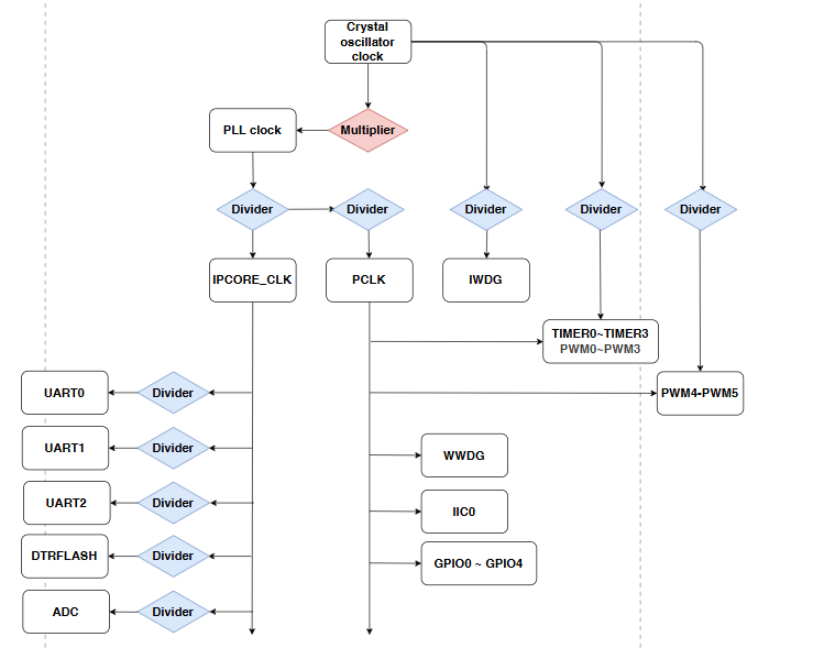
- Some peripherals derive from IPCORE_CLK, some from PCLK, and some can derive directly from the oscillator. Details are listed below.
| Peripheral | Description | Clock source | Divider width | Default divider |
|---|---|---|---|---|
| IPCORE_CLK | AHB bus clock (main clock) | From PLL | 6 bits (0~63) | 0 (÷1) |
| PCLK | APB bus clock | From IPCORE_CLK | 4 bits (0~15) | 2 |
| UART | Determines baud rate | From IPCORE_CLK | 6 bits (0~63) | 8 |
| PWM | Determines output frequency | From PCLK (fixed ÷1) or oscillator (programmable) | 7 bits (0~127) | 16 |
| TIMER | Determines counter rate | From PCLK (fixed ÷1) or oscillator (programmable) | 7 bits (0~127) | 16 |
| IWDG | Determines counter rate | From oscillator | 7 bits (0~127) | 16 |
| DTRFLASH | Determines CLK frequency | From IPCORE_CLK | 3 bits (0~7) | 2 |
| ADC | Determines sampling rate | From IPCORE_CLK | 6 bits (0~63) | 12 |
| WWDG | Window watchdog counter | From PCLK (fixed ÷1) | - | - |
| IIC | SCL frequency | From PCLK (fixed ÷1) | - | - |
| GPIO | I/O toggle rate | From PCLK (fixed ÷1) | - | - |
- You can read IPCORE_CLK and other clocks via APIs, then compute each peripheral’s default clock using its divider.
#include "platform_config.h"

void device_clk_test()
{
    // Two ways to get IPCORE_CLK (main clock)
    #if 0
    uint32_t ipcore_clk = dpmu_get_pll_frequency() / 1;      // Default ÷1 from PLL
    #else
    uint32_t ipcore_clk = get_ipcore_clk();                  // Read via API
    #endif

    // Two ways to get PCLK
    #if 0
    uint32_t pclk = ipcore_clk / 2;                          // Default ÷2 from main clock
    #else
    uint32_t pclk = get_apb_clk();                           // Read via API
    #endif

    // Two ways to get UART clock
    #if 0
    uint32_t uart_clk = ipcore_clk / 2;                      // SDK uses ÷2
    #else
    uint32_t uart_clk = get_ahb_clk() / 2;                   // AHB equals IPCORE_CLK
    #endif

    // Get ADC clock
    uint32_t adc_clk = ipcore_clk / 12;                      // Default ÷12

    // Get DTRFLASH clock
    uint32_t system_dtrflash_clk = ipcore_clk / 1 ;          // SDK uses ÷1
    uint32_t dtrflash_out_clk = system_dtrflash_clk / 2      // Controller internal ÷2 (2/4/6/8 optional); output CLK ≤ main/2

    // Two ways to get PWM/TIMER clock
    #if 0
    uint32_t pwm_timer_clk = pclk;                           // If source is PCLK
    #else
    uint32_t pwm_timer_clk = get_src_clk() / 16;             // If source is oscillator, default ÷16
    #endif

    // Get IWDG clock
    uint32_t iwdg_clk = get_src_clk() / 16;                  // Default ÷16

    // Get WWDG/IIC/GPIO clocks
    uint32_t wwdg_clk = pclk;
    uint32_t iic_clk = pclk;
    uint32_t gpio_clk = pclk;
}
- To change peripheral dividers, refer to the following example:
#include "ci130x_scu.h"
#include "ci130x_dpmu.h"
#include "ci130x_system.h"
#include "platform_config.h"

void device_div_test()
{
    scu_set_div_parameter(IPCORE_BASE,2);       // Set IPCORE_CLK ÷2

    uint32_t ipcore_clk = dpmu_get_pll_frequency() / 2;
    set_ipcore_clk(ipcore_clk);                 // Update global main clock
    set_apb_clk(ipcore_clk);

    scu_set_div_parameter(APB_BASE,2);          // Set PCLK ÷2
    set_apb_clk(ipcore_clk/2);                  // Update PCLK global

    scu_set_div_parameter(HAL_UART0_BASE,2);    // Set UART0 ÷2
    scu_set_div_parameter(HAL_UART1_BASE,2);    // Set UART1 ÷2
    scu_set_div_parameter(HAL_UART2_BASE,2);    // Set UART2 ÷2
    scu_set_div_parameter(HAL_PWM0_BASE,4);     // Set PWM0/1/2/3 and TIMER0/1/2/3 ÷4 (shared)
    scu_set_div_parameter(HAL_PWM4_BASE,4);     // Set PWM4/5 ÷4 (shared)
    scu_set_div_parameter(HAL_IWDG_BASE,6);     // Set IWDG ÷6
    scu_set_div_parameter(HAL_DTRFLASH_BASE,2); // Set DTRFLASH ÷2
    scu_set_div_parameter(HAL_ADC_BASE,8);      // Set ADC ÷8
}
5. I2S Clock Configuration
5.1 I2S Clock Divider Relationships
- First, a few I2S terms used below:
- I2S has independent clock and data signals: MCLK, SCK, LRCK, SDI, SDO.
- MCLK: Master clock, typically 128/192/256/384 × sample rate (LRCK). For 16 kHz with ×256, MCLK = 4.096 MHz.
- SCK: Bit clock; one bit per cycle, typically 32× or 64× LRCK. For 16 kHz with ×64, SCK = 1.024 MHz.
- LRCK: Frame clock; in I2S format, LRCK=0 indicates left channel and LRCK=1 indicates right channel.
-
For more on I2S, see Audio Digital Transport Bus (IIS).
-
I2S clock division has a dedicated API set and supports independent clock paths per IIS instance. Below is the master‑mode clock configuration flow.
-
The diagram below shows the I2S clock division flow.
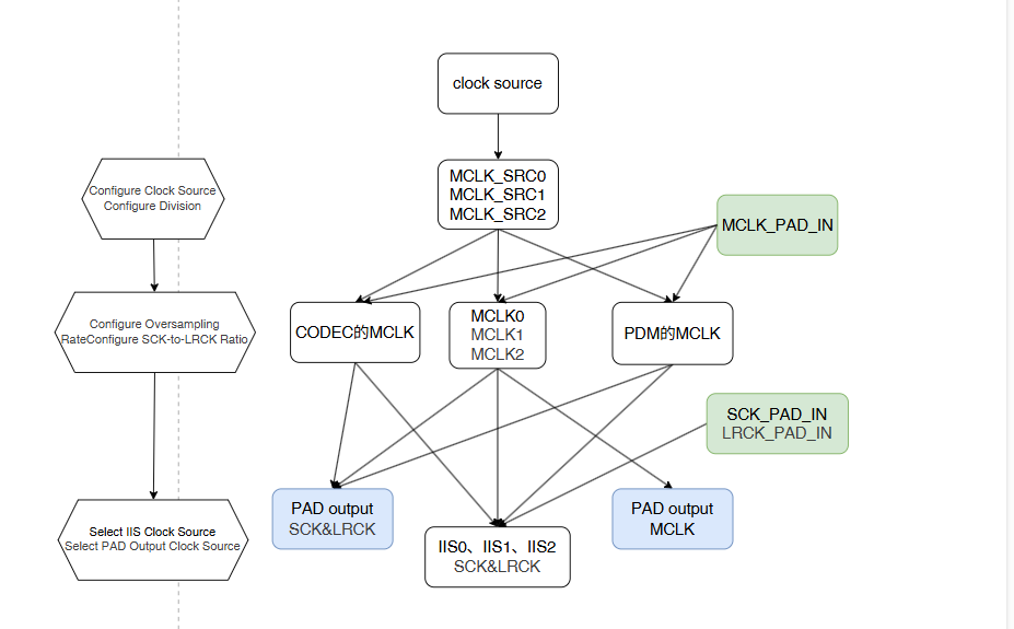
- Stage 1 clock source has four options:
// In #include "ci130x_scu.h"

/**
 * @brief MCLK SRC clock source selection
 */
typedef enum
{
    //! From IPCORE main clock
    IIS_SRC_SOURCE_IPCORE   = 0,
    //! From EXT_OSC (external crystal)
    IIS_SRC_SOURCE_EXT_OSC  = 1,
    //! From INTERNAL RC (internal oscillator)
    IIS_SRC_SOURCE_INTER_RC = 2,
    //! From PAD IN (IIS_MCLK_PAD input)
    IIS_SRC_SOURCE_PAD_IN   = 3,
}IIS_Src_Source_t;
- Stage 2 SRC_MCLK has four options. The first three allow independent source and divider (IIS_Src_Source_t); the fourth is from PAD. These can source CODEC, PDM, and MCLK0~MCLK3:
//位于#include "ci130x_scu.h"中

/**
 * @brief MCLK source selection
 */
typedef enum
{
    //! From SRC0
    IIS_MCLK_SOURCE_SRC0    = 0,  // Programmable divider, 10-bit (0~1023)
    //! From SRC1
    IIS_MCLK_SOURCE_SRC1    = 1,  // Programmable divider, 10-bit (0~1023)
    //! From SRC2
    IIS_MCLK_SOURCE_SRC2    = 2,  // Programmable divider, 10-bit (0~1023)
    //! From PAD IN
    IIS_MCLK_SOURCE_PAD_IN  = 3,  // No divider; from IIS_MCLK_PAD
}IIS_Mclk_Source_t;
- Stage 3 MCLK selection has three options, each supporting independent oversampling (4 options) and SCK/LRCK ratio (2 options):
//位于#include "ci130x_scu.h"中

/**
 * @brief MCLK selector
 */
typedef enum
{
    //! MCLK0
    IIS_MCLK_MCLK0    = 0,
    //! MCLK1
    IIS_MCLK_MCLK1    = 1,
    //! MCLK2
    IIS_MCLK_MCLK2    = 2,
}IIS_Mclk_t;

/**
 * @brief IIS MCLK oversampling rate selection
 */
typedef enum
{
    //! FS×128
    IIS_MCLK_FS_128   = 0,
    //! FS×192
    IIS_MCLK_FS_192   = 1,
    //! FS×256
    IIS_MCLK_FS_256   = 2,
    //! FS×384
    IIS_MCLK_FS_384   = 3,
}IIS_Mclk_Fs_t;

/**
 * @brief IIS SCK/LRCK frequency ratio
 */
typedef enum
{
    //! SCK/LRCK = 32
    IIS_SCK_LRCK_WID_32  = 0,
    //! SCK/LRCK = 64
    IIS_SCK_LRCK_WID_64  = 1,
}IIS_Sck_Lrck_Wid_t;
- Stage 4 SCK/LRCK source per IIS has six options; these can also drive PAD outputs:
//位于#include "ci130x_scu.h"中

/**
 * @brief IIS SCK/LRCK output source
 */
typedef enum
{
    //! SCK/LRCK generated by MCLK0
    IIS_CLK_SOURCE_MCLK0     = 0,
    //! SCK/LRCK generated by MCLK1
    IIS_CLK_SOURCE_MCLK1     = 1,
    //! SCK/LRCK generated by MCLK2
    IIS_CLK_SOURCE_MCLK2     = 2,
    //! SCK/LRCK from PAD input
    IIS_CLK_SOURCE_PAD_IN    = 3,
    //!codec_ad_sck_in
    IIS_CLK_SOURCE_CODEC_AD  = 4,
    //!codec_da_sck_in
    IIS_CLK_SOURCE_CODEC_DA  = 5,
    //!pdm_sck_in
    IIS_CLK_SOURCE_PDM       = 6,
}IIS_Clk_Source_t;
5.2 I2S Clock Example Code
- One-step configuration API definition:
//位于#include "ci130x_scu.h"中

void iis_clk_config(IIS_Clk_ConfigTypedef* config);
- Example: Configure IIS0 clock path in master mode using the one-step API:
#include "ci130x_scu.h"
#include "platform_config.h"

void init_iis_clk_sample()
{
    uint32_t sample_rate = 16000;                       // Audio sample rate
    uint32_t ipcore_clk = get_ipcore_clk();             // Source clock frequency
    uint32_t fs = 256;

    float div = ((float)ipcore_clk / (float)sample_rate / (float)fs);  // Divider from source, sample rate, and oversampling

    IIS_Clk_ConfigTypedef config = {0};
    config.device_select = IISNum0;                     // Select IIS0 clock path
    config.model_sel = IIS_MASTER;                      // Master mode
    config.src_cfg.source = IIS_SRC_SOURCE_IPCORE;      // Use IPCORE_CLK as source
    config.mclk_cfg.src = IIS_MCLK_SOURCE_SRC0;         // Use MCLK_SRC0
    config.mclk_cfg.mclk = IIS_MCLK_MCLK0;              // Use MCLK0 and SCK/LRCK ratio
    config.mclk_cfg.fs = IIS_MCLK_FS_256;               // Oversampling ×256
    config.mclk_cfg.sck_lrck = IIS_SCK_LRCK_WID_64;     // SCK/LRCK = 64
    config.clk_cfg = IIS_CLK_SOURCE_MCLK0;              // Use MCLK0-generated SCK/LRCK for IIS0
    config.mclk_mode = IIS_MCLK_OUT;                    // Output MCLK via PAD
    config.clk_mode = IIS_SCKLRCK_OUT;                  // Output SCK/LRCK via PAD
    config.src_cfg.source_div = (uint16_t)div;          // Divider configuration
    iis_clk_config(&config);

    uint32_t lrck = sample_rate;                        // LRCK frequency
    uint32_t sck = sample_rate * 64;                    // SCK frequency
    uint32_t mclk = sample_rate * fs;                   // MCLK frequency
}
- Multi-step configuration API definitions:
//位于#include "ci130x_scu.h"中

void scu_iis_src_config(IIS_Src_Config_t *config,IIS_Mclk_Source_t src);        // Select MCLK_SRC0/1/2 and set source/divider
void scu_iis_mclk_config(IIS_Mclk_Config_t *config);                            // Select MCLK0/1/2 and set FS and SCK/LRCK ratio
void scu_iis_clk_config(IISNumx device, IIS_Clk_Source_t clk_source);           // Set SCK/LRCK source for IIS0/1/2
void scu_iis_codec_mclk_config(Codec_Channel_t channel, IIS_Mclk_Source_t src); // Set CODEC AD/DA MCLK source
void scu_iis_pdm_mclk_config(IIS_Mclk_Source_t src);                            // Set PDM MCLK source
void scu_iis_pad_mclk_config(IIS_Mclk_Source_t src, IIS_Clk_Mode_t mode);       // Configure MCLK PAD I/O mode and output source
void scu_iis_pad_clk_config(IIS_Clk_Source_t clk_source, IIS_Clk_Mode_t mode);  // Configure SCK/LRCK PAD I/O mode and output source
- Internally, the one-step API calls the same multi-step routines.
6. Notes
-
Usually configure the oscillator selection before configuring the PLL.
-
When changing peripheral dividers, disable the peripheral clock first, modify the divider, then re-enable the clock.