CI-G24XGS02J Module Datasheet
Module Introduction
Overview
This module is a general-purpose, portable, low-power, high-performance voice recognition module with BLE functionality, developed for cost-effective offline voice applications. The model is CI-G24XGS02J, featuring CI23242 as the main chip, capable of recognizing up to 300 offline voice commands (the exact number depends on the specific model).
Key features of the module include:
- Compact size of 30mm × 40mm
- Operating voltage range: 3.6V - 5.5V
- Equipped with one microphone input, one speaker output, and one 5V power supply with UART interface (5V level)
- Plug-and-play functionality when connected to a microphone and speaker
- Can be directly connected to the main control board via connectors using 5V power supply, UART communication, or GPIO control without soldering
- Includes two 3.5mm screw holes for easy fixing and installation
Additional features: - Supports BLE functionality - Features offline neural network computation - Single-microphone noise reduction and enhancement - 360° omnidirectional sound pickup - Environmental noise suppression for accurate voice recognition in noisy environments - Independent of network connection with low latency and high performance - Achieves over 97% recognition rate - Supports up to 10m long-distance recognition - Response time as fast as 0.2 seconds - Suitable for products with energy efficiency requirements and battery-powered devices - Supports BLE protocol for control via WeChat Mini Program - Industrial-grade components for high reliability
| Module Selection | Local Commands ≤100 | Local Commands ≤300 |
|---|---|---|
| Single-mic Offline Voice BLE Module with Connector | CI-G241GS02J | CI-G242GS02J |
Main Chip Introduction
CI23242 is specifically designed for voice processing, supporting local voice recognition in multiple languages including Chinese, English, and Japanese. They are widely used in home appliances, lighting, toys, wearable devices, industrial applications, and automotive products for voice interaction, control, and various intelligent voice solutions.
The chips integrate Chipintelli’s self-developed BNPU V3.5 neural network processor and CPU core, with a system frequency up to 210MHz, built-in 288KB SRAM, PMU power management unit, RC oscillator, single-channel high-performance low-power Audio Codec, and multiple peripheral interfaces including UART, I2C, PWM, and GPIO. The chips also feature high-performance, low-power Bluetooth BLE. With minimal external components required, they offer excellent cost-performance for various intelligent voice product solutions.
For more detailed information about CI23242 chip, please visit:
Application Scenarios
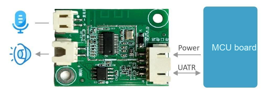
The module can be used as a voice recognition front-end combined with customer’s main control board solution, or as a single-chip main control module for lighting, toys, and other applications. It requires an external microphone, speaker, and 5V power supply.
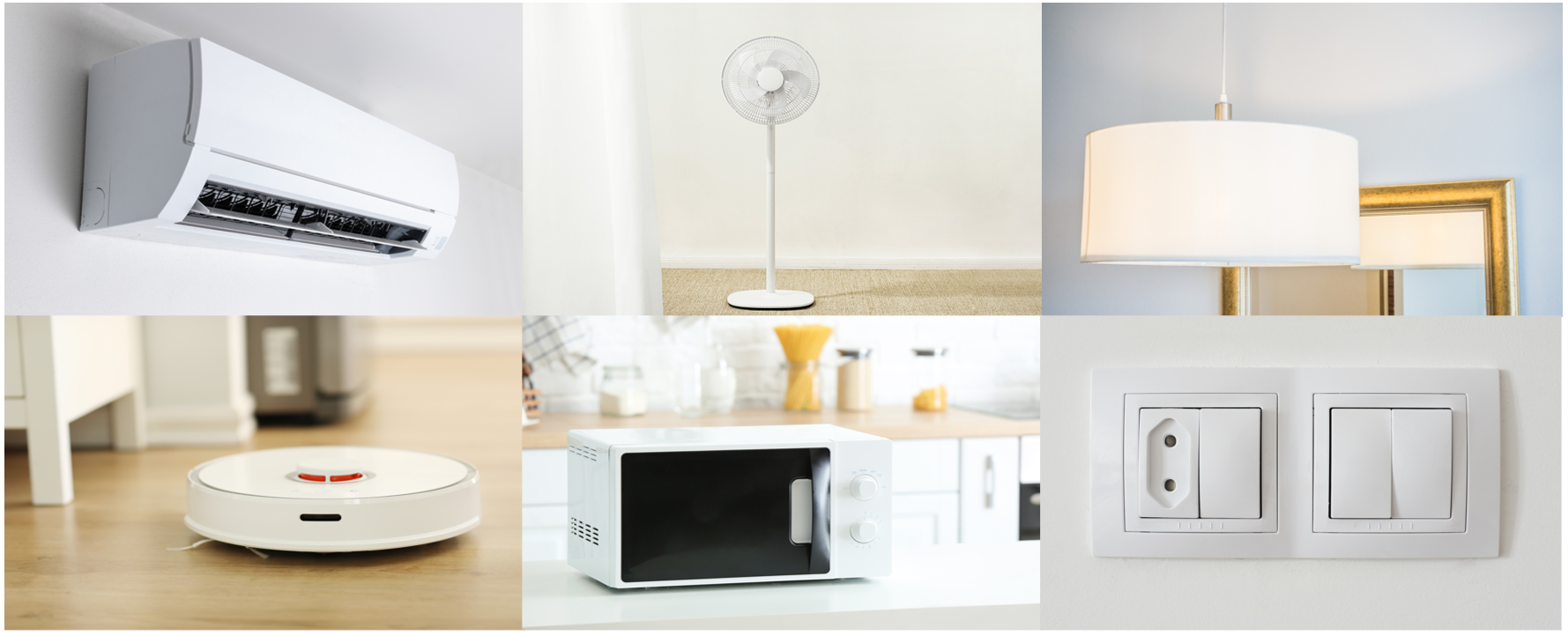
The CI-G24XGS02J series modules support 100-300 offline voice recognition commands depending on the chip model, suitable for various terminal products such as smart fans, heating tables, drying racks, small household appliances, toys, and lighting.
Module Specifications
Physical Layout
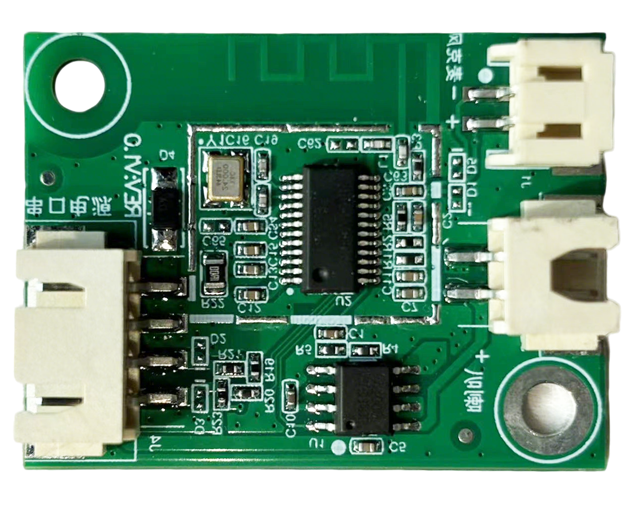
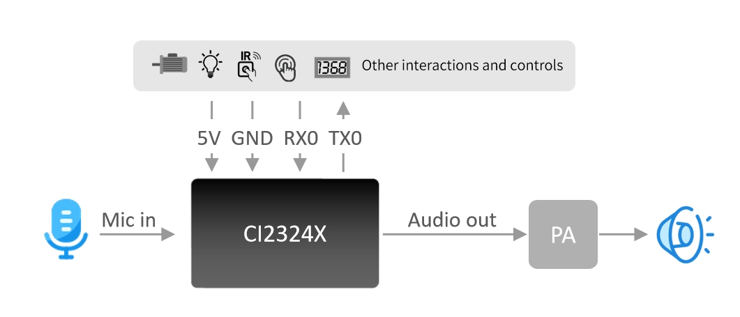
As shown in Figure 4, the voice recognition module features single-sided SMT mounting, primarily consisting of the voice recognition chip and audio power amplifier. Voice commands are input through the microphone, processed by the voice recognition IC for voice recognition and command processing, and the feedback audio is sent to the audio power amplifier to drive the speaker. The audio power amplifier supports a maximum output power of 1.5W@8Ω and 2W@4Ω.
Module Dimensions
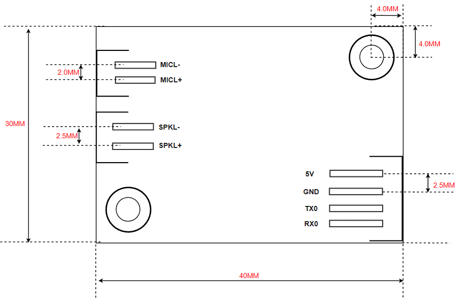
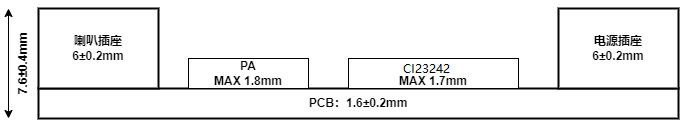
As shown in Figure 5, the module has a rectangular shape with dimensions of 30±0.3mm × 40±0.15mm, PCB thickness of 1.6±0.2mm, and module height of 7.6±0.4mm. Users can design the structure based on these dimensions.
Module Hardware Interface Definition
The module includes the following functional interfaces:
-
Two-wire single microphone interface using a 2.0mm pitch female connector. For optimal voice recognition performance, it is recommended to use a microphone with -32±3dB sensitivity and SNR ≥65dB. Click ☞Reference Microphone Devices for more information.
-
Two-wire single speaker interface using a 2.5mm pitch female connector. For optimal audio output, it is recommended to use a speaker with an acoustic cavity. Click ☞Reference Speaker Devices for more information.
-
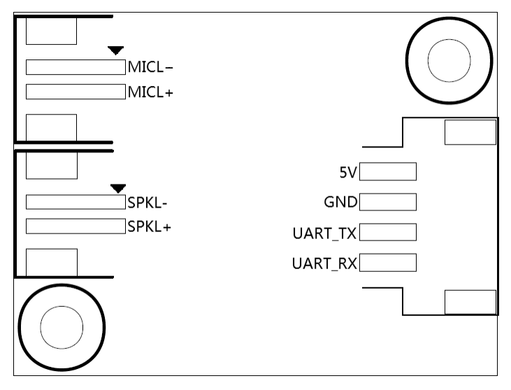
Four-wire power supply and UART interface using a 2.5mm pitch female connector. The pin configuration is shown in Figure 6. The UART pins in this interface can also be configured as GPIO pins.
Detailed pin descriptions are provided in Table 2:
| Pin # | Pin Name | I/O Type | Drive Capability | Default Power-on State | Function Definition |
|---|---|---|---|---|---|
| 1 | 5V | P | - | - | 5V Power Supply |
| 2 | GND | P | - | - | Ground |
| 3 | UART_TX | IO, T+U | 4mA | IN, T+U | 1. UART0_TX 2. PB5 |
| 4 | UART_RX | IO, T+U | 4mA | IN, T+U | 1. UART0_RX 2. PB6 |
| 5 | MICL- | - | - | - | Microphone Negative |
| 6 | MICL+ | - | - | - | Microphone Positive |
| 7 | SKPL- | - | - | - | Speaker Output |
| 8 | SKPL+ | - | - | - | Speaker Output |
Legend for the table above:
I: Input
O: Output
IO: Bidirectional
P: Power or Ground
T+D: Tristate plus pull-down
T+U: Tristate plus pull-up
OUT: Power-on defaults to output mode
IN: Power-on defaults to input mode
Module Electrical Characteristics
| Parameter | Condition | Min | Typ | Max | Unit | Note |
|---|---|---|---|---|---|---|
| Module Supply Voltage | / | 3.6 | 5 | 5.5 | V | NOTE1 |
| Module Current in Playback Mode (Normal Volume) | 4Ω 3W Speaker | / | 100 | / | mA | NOTE2 |
| Module Operating Current | / | / | 55 | / | mA | NOTE3 |
| Chip I/O Interface Voltage | / | 3 | 3.3 | 3.6 | V | / |
| Module UART Interface Voltage | / | 4.5 | 5 | 5.5 | V | / |
NOTE1: 5V is the typical supply voltage for the module. Input voltage exceeding 5.5V may damage the module.
NOTE2: The module can draw up to 250mA during audio playback. For reliable operation, provide a power supply capable of delivering 500mA (2x margin).
NOTE3: Typical value is measured in mute state. Maximum value is measured during recognition and playback.
Bluetooth Electrical Characteristics
| Parameter | Condition | Min | Typ | Max | Unit | Note |
|---|---|---|---|---|---|---|
| Frequency Range | / | 2.3 | / | 2.6 | GHz | / |
| Current in TX 0dBm | / | / | 2.5 | / | mA | / |
| Current in RX 1Mbps | / | / | 2.8 | / | mA | / |
| Current in Power Down | / | / | 2 | / | μA | / |
| Maximum Output Power | 50Ω | / | +5 | / | dBm | / |
Module Temperature and Humidity Parameters
The temperature and humidity parameters for CI-G24XGS02J are consistent, as shown in Table 4.
| Parameter | Min | Typ | Max | Unit | Note |
|---|---|---|---|---|---|
| Operating Temperature | -40 | 25 | 85 | °C | / |
| Storage Temperature | -40 | 25 | 100 | °C | / |
| Storage Humidity | 0% | / | 5% | RH | / |
Module Application
Power-on and Startup
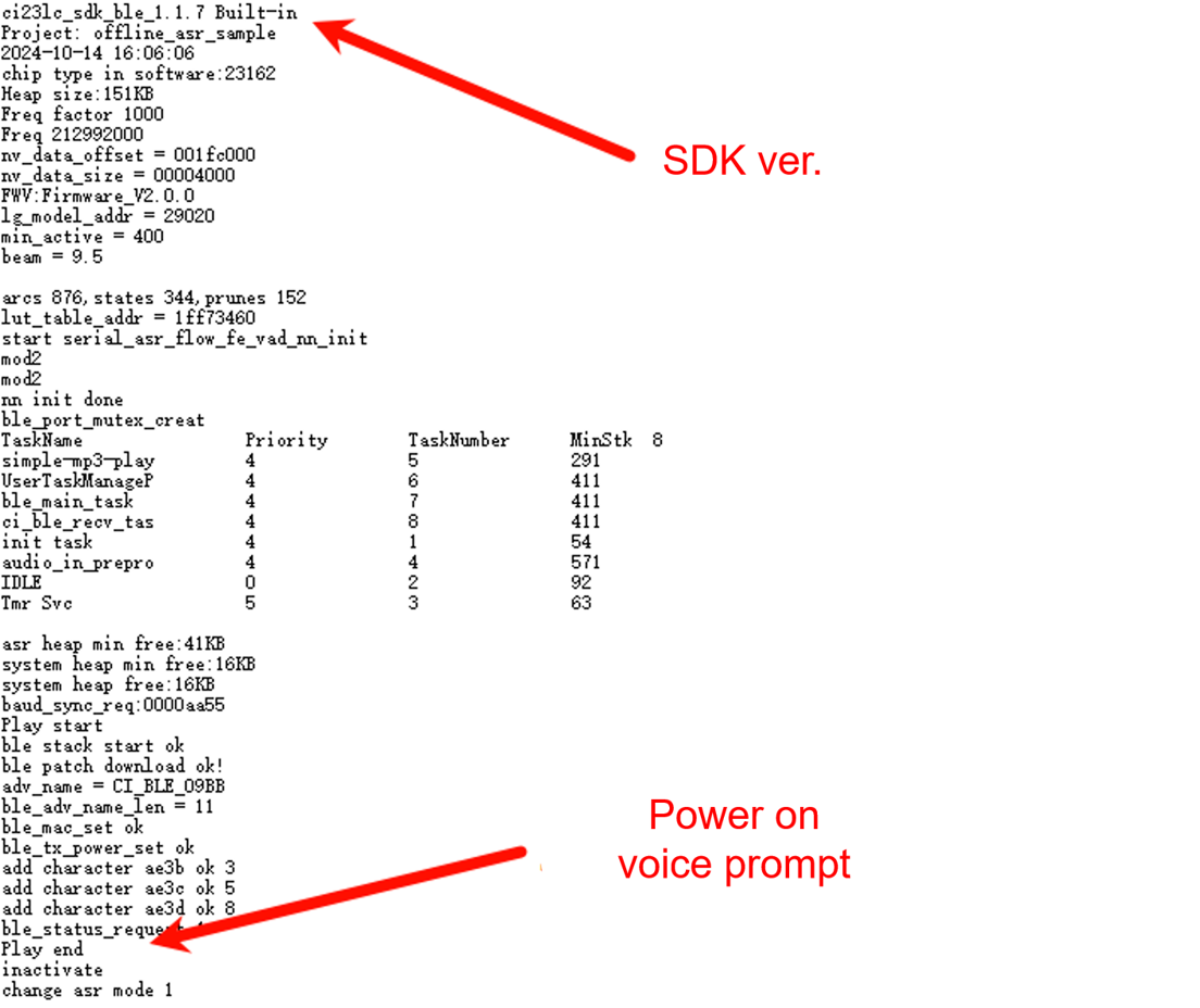
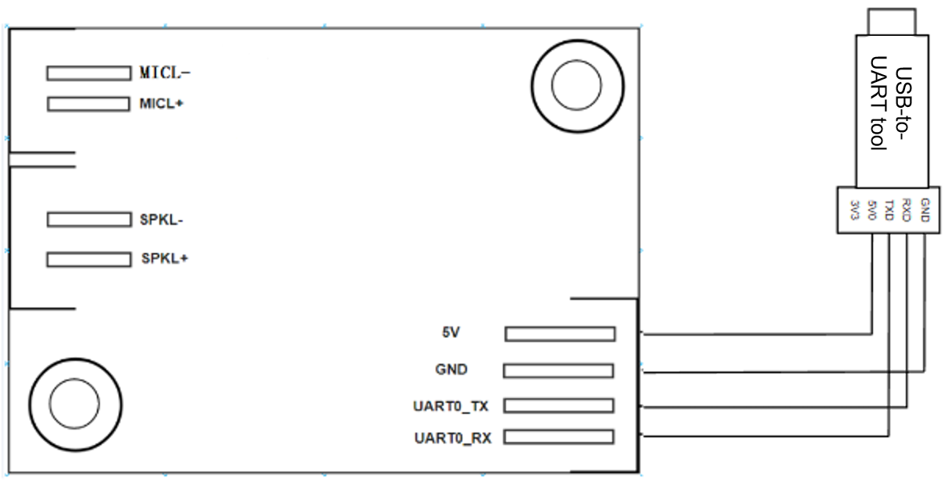
To use the module, connect a speaker and microphone, then supply 5V power through the power connector. The module will start up upon power-on, and the speaker will play a prompt tone. The UART port will output startup information, which can be viewed using a USB-to-UART converter and terminal software on a computer, as shown in Figure 7. Note that the module’s UART interface operates at 5V level and does not require level shifting when interfacing with 5V systems.
The voice recognition chip and audio power amplifier on the module are powered by a 5V supply. The 5V power supply must provide a rated current of 500mA with stable voltage and ripple below 300mV.
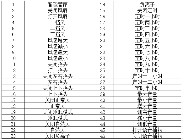
Default Command Words
For production modules, custom firmware with specific command words is typically pre-installed. If not specified, the module comes with default firmware containing test command words, as partially shown in Figure 8.
Default UART Communication Protocol
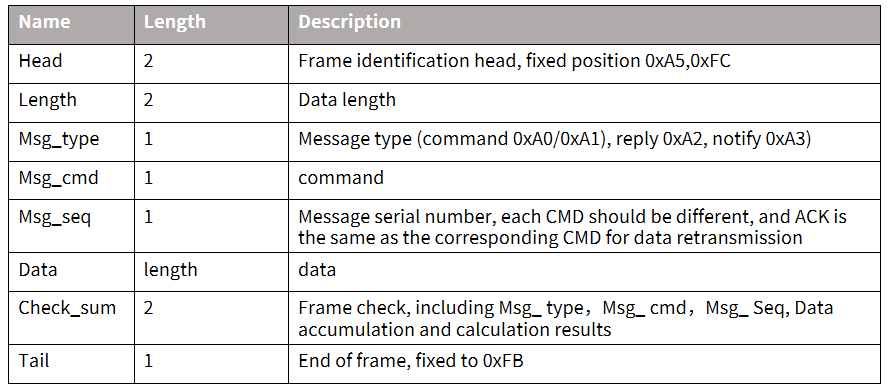
The module’s default firmware supports a UART communication protocol for host communication with the following features:
- Complete transmission packets including header, footer, length, checksum, message type, and sequence number
- Support for variable-length commands for easy expansion
- Message types (command, notification, response)
- Command messages with configurable ACK responses (notifications do not require ACK)
- Message format compatible with bootloader upgrade protocol, distinguished by header
- Default baud rate: 9600 bps
- Note: Only UART0 interface is reserved, which is by default used for debug output. To use UART0 for the protocol interface, code modification is required. Refer to the UART protocol section in the ☞CI13LC Series Chip SDK for implementation details.
- Supported commands: Query protocol version, query system version, set volume (volume levels defined in user_config.h), play local prompt tones, reset command, etc. The protocol format is shown below:
Example 1:
A5 FC 07 00 A0 91 18 01 55 E0 01 00 00 1B 9B 02 FB
Parsed as: - A5 FC: Header - 07 00: 7 bytes of valid data - A0: Command word information - 91: Command number 0x91 (contains command word data) - 18: Packet sequence number (0x08th transmission, increments with each transmission) - 01 55 E0 01 00 00: Unique data for the current command word - 1B: Command word threshold - 9B 02: Checksum - FB: End marker
Note
If only the command word and threshold are needed, focus on the 7 bytes of valid data highlighted in blue.
Example 2:
A5 FC 02 00 A3 9A 17 00 B1 05 02 FB
Parsed as: - A5 FC: Header - 02 00: 2 bytes of valid data - A3: Notification data - 9A: Command number 0x9A (voice module content change) - 17: Packet sequence number (0x07th transmission, increments with each transmission) - 00 B1: Valid data (indicates entering wake-up state) - 05 02: Checksum - FB: End marker
Note
This is notification data. Users can choose whether to use this information based on their needs.
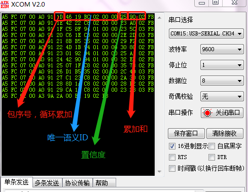
For more protocol data parsing, refer to the UART protocol section in the ☞CI13LC Series Chip SDK. Below is a reference screenshot of protocol data:
Software Development
The default firmware included with the module is primarily for initial evaluation. For software development, users need to register and log in to the Chipintelli AI Platform (https://aiplatform.Chipintelli.com) for rapid voice firmware development. The SDK and related hardware documentation can be downloaded from the “Development Resources” section of the platform.
For first-time users of the Chipintelli AI Platform, it is recommended to review the Beginner’s Guide to understand the development process. Additional video tutorials are available in the Video Tutorials section.
Key development resources include: * SDK development package downloads * Model development (language model + acoustic model) * Voice synthesis * Command word information table and audio file association * Firmware packaging
For detailed development process, please refer to ☞CI13LC Series Chip SDK.
Firmware Flashing
Pre-flashing Preparation
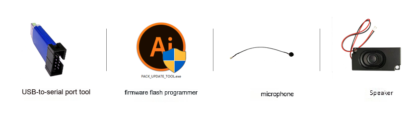
Before flashing the module, prepare the following items:
- Module to be flashed
- USB-to-UART converter
- Firmware flashing tool (pack_update_tool.exe)
- Firmware file (*.bin format)
- 2.0mm pitch microphone
- 2.5mm pitch speaker
- DuPont wires
Hardware Connection and Flashing
For voice firmware flashing, connect the USB-to-UART converter’s power, ground, and UART pins to the corresponding pins on the module. Note that the USB-to-UART converter’s RXD and TXD should be connected to the module’s UART0_TX and UART0_RX respectively, as shown in the figure below.
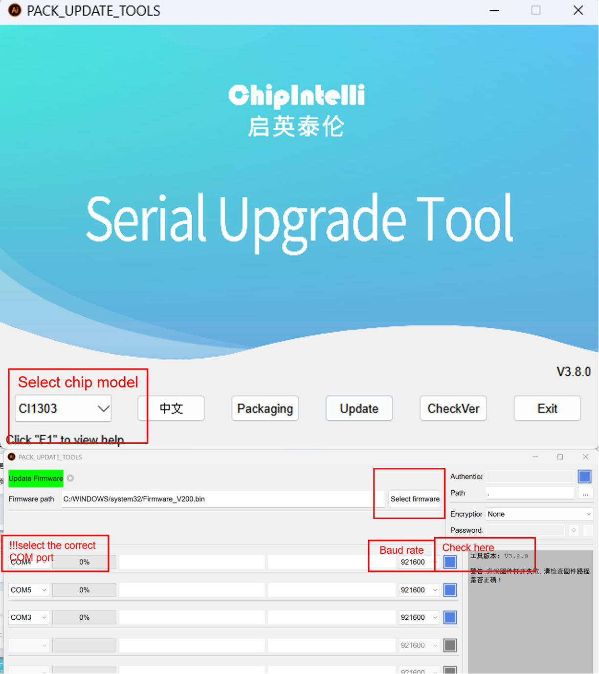
Open the firmware flashing tool (PACK_UPDATE_TOOL.exe, available in the SDK development package under CI231X_SDK\tools), select the corresponding chip model, click the Firmware Update button, choose the prepared firmware file, and confirm the COM port assigned to the USB-to-UART converter. After completing these preparations, power on the module to enter Firmware Update mode and begin the flashing process. If the computer cannot recognize the USB-to-UART converter, install the appropriate drivers first.
Post-flashing Function Test
-
Voice Function Test: After flashing, test the module’s functionality to verify the firmware installation. Connect a microphone and speaker, power on the module, and check for the startup prompt tone. Test the wake word and command words to ensure proper recognition. If all functions work as expected, the module is functioning correctly. If not, investigate the issue.
-
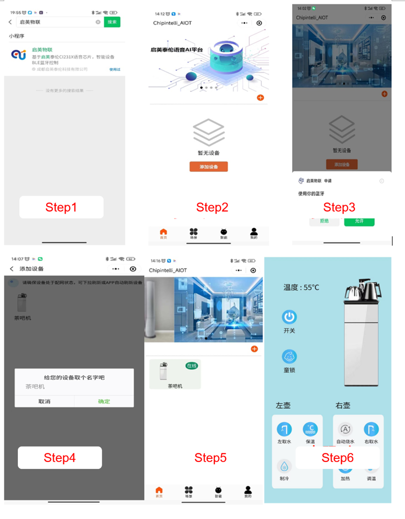
Bluetooth Function Test:
- Search for the “Chipintelli IoT” or “AI Voice Control” mini-program in WeChat
- Enable Bluetooth permissions (some phones may require location permissions)
- Turn on the phone’s Bluetooth
- Add a device by clicking the “+” button or the “Add Device” button
- Enter the device scanning interface and select the detected device (Currently supported devices include: tea makers, air conditioners, lights, fans, etc.)
- Confirm device connection
- Name the device
- Return to the home page after successful connection
- Click on the added device to access the device control interface
Troubleshooting
This section lists Troubleshooting when using the module.
- Module Cannot Be Flashed or Updated If this issue occurs, check the following: 1. Ensure TX, RX, and GND are properly connected, select the correct COM port in the flashing tool (Figure 13), then apply 5V power. 2. Verify the UART pins are correctly connected (TX/RX not swapped), the USB-to-UART driver is properly installed, and the correct COM port is selected in the flashing tool. 3. If the issue persists, use a multimeter to check the module’s power supply voltages (5V, 3.3V, 1.1V) at the test points shown below. If any voltage is incorrect, the module may be faulty and should be replaced or repaired. If all checks are normal, contact technical support for assistance.

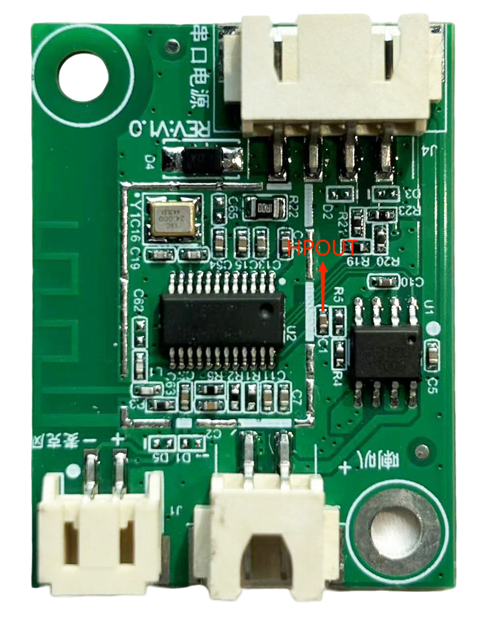
- No broadcast After Flashing If this issue occurs, check the following: 1. Verify the flashed firmware is compatible with the board. 2. Ensure the speaker is properly connected and powered. Use an oscilloscope to measure the audio output test points on the main chip. If there is no output, check the firmware. If there is output, inspect the audio power amplifier for soldering issues. If the audio power amplifier is faulty, replace it and retest. The measurement points are shown below. If the issue persists, contact technical support.
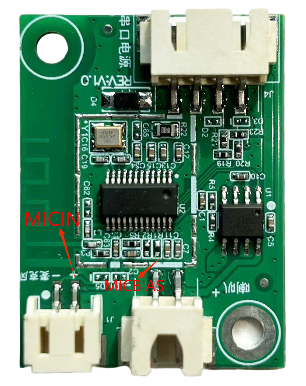
- Audio Output Present But No Command Word Recognition 1. Check the microphone and connector connections. 2. Verify the microphone polarity matches the module’s markings. 3. Use a multimeter to measure the MICBIAS pin voltage (should be around 2.8V) and an oscilloscope to check the microphone input waveform (set to 100mV/div). If the signal is normal, check the firmware. If the signal is abnormal, inspect the board for physical damage. The measurement points are shown below. If the issue persists, contact technical support.
Additional Application Notes
Since CI23242 chip has high ESD ratings and the module is designed for user expansion, no additional ESD protection devices are included. For products requiring high ESD protection, add ESD devices externally. It is recommended to wear anti-static wrist straps or gloves during inspection and soldering. Reserve space for ESD protection devices at the connector positions on the main board to ensure product reliability.
Ensure correct connections for the microphone, speaker, and power supply to prevent reverse connections. Avoid short circuits on the test points on the back of the module.
Note that the module’s UART interface operates at 5V level. Use a 5V-level UART for communication. For software debugging, use a USB-to-UART converter and add UART print commands in the SDK software. After compiling and flashing the firmware, proceed with debugging and verification.
Production Guide, Storage, and Ordering Information
Production Guide
The module features integrated connectors for easy assembly. Simply insert the microphone, speaker, and power/communication connectors into their respective ports. The design includes foolproof connectors to prevent incorrect connections. Wear anti-static gloves and wrist straps during assembly, and ensure connectors are fully inserted with appropriate force. Open the vacuum-sealed anti-static bag only when ready to begin assembly.
Storage Conditions
The module is vacuum-sealed and can be stored in a non-condensing environment below 40°C/90% RH. The module’s Moisture Sensitivity Level (MSL) is 3. If the vacuum bag is opened or leaks, follow MSL Level 3 handling procedures.
Packaging and Ordering Information
| Product Model | Packaging Method | Modules per Tray | Modules per Package | Modules per Box |
|---|---|---|---|---|
| CI-G241GS02J | Tray + Anti-static Bag + Carton | 40pcs | 10 trays 400pcs in total | 3 bags 1200pcs in total |
| CI-G242GS02J | Tray + Anti-static Bag + Carton | 40pcs | 10 trays 400pcs in total | 3 bags 1200pcs in total |
Procurement and Technical Support
If you want to purchase samples of our products, please click ☞Sample Purchase .
If you want to get technical support, please log in to ☞Chipintelli AI Speech Development Platform .