CI-D1XGS08J Module Datasheet
Module Introduction
Overview
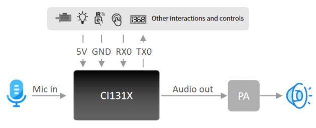
This module is a general-purpose, portable, low-power, high-performance voice recognition module developed for low-cost offline voice applications. The model is CI-D1XGS08J, based on CI1311/CI1312 main chips, and supports recognition of up to 300 offline command words (the supported number varies by model).
This module has the following features:
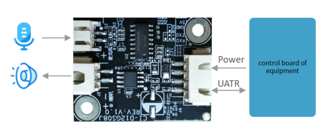
Compact size of 30 mm × 40 mm; operating voltage 3.6 V–5.5 V. The board integrates a power amplifier, with one microphone interface, one speaker interface, and one 5 V power and UART interface. The module can be used directly by plugging in a microphone and speaker, or you can connect the UART to the product’s main control board via the connector and power it from the board’s 5 V supply. It supports UART communication or GPIO control, with no soldering required. Two 3.5 mm screw holes are provided for easy mounting.
- The main chip supports offline neural network computation, single-microphone noise reduction and enhancement, and 360-degree omnidirectional pickup, suppressing environmental noise to ensure recognition accuracy in noisy environments. Offline recognition does not rely on a network, with low latency and high performance, enabling over 97% recognition accuracy, up to 10 m long-distance recognition, and response time as fast as 0.2 s.
- Applicable to products with energy-efficiency requirements and battery-powered products.
- Built with industrial-grade components for high reliability.
| Module options | Up to 100 local commands | Up to 300 local commands |
|---|---|---|
| Single-mic offline voice module with connectors | CI-D11GS08J | CI-D12GS08J |
Main Chip Introduction
CI1311 and CI1312 are AI chips specifically designed for voice processing. They support local voice recognition and multiple global languages including Chinese, English, and Japanese. They are widely applicable to home appliances, lighting, toys, wearables, industrial, and automotive products for voice interaction, control, and various intelligent voice solutions.
CI1311/CI1312 integrate chipintelli’s self-developed BNPU V3 neural network processor and a CPU core, with system frequency up to 220 MHz, up to 640 KByte on-chip SRAM, an integrated PMU power management unit and RC oscillator, a dual-channel high-performance low-power Audio Codec, and multiple peripheral control interfaces including UART, I2C, I2S, PWM, GPIO, and PDM. Only a few external components (resistors/capacitors) are required to build various intelligent voice hardware solutions with excellent cost performance.
For more detailed information about CI1311/CI1312, please click the link below:
☞CI1311 & CI1312 Chip Datasheet
Module Application Scenarios
This module can be used as a voice recognition front-end together with the customer’s main control board, or as a standalone main control module for solutions such as lighting and toys. For application, connect an external microphone and speaker, and power it using an external 5 V supply.
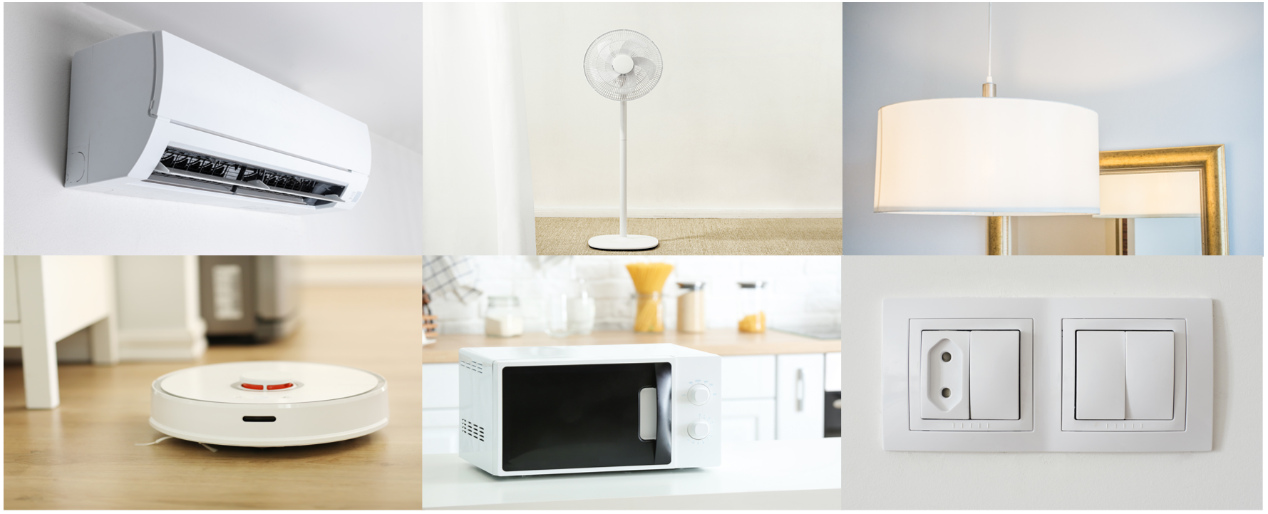
The CI-D1XGS08J module supports up to 300 offline voice commands and can be used in products with modest command requirements such as electric fans, heating tables, clothes dryers, small appliances, toys, and lighting.
Module Specifications
Module Photos
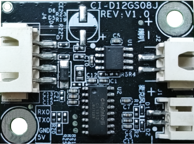
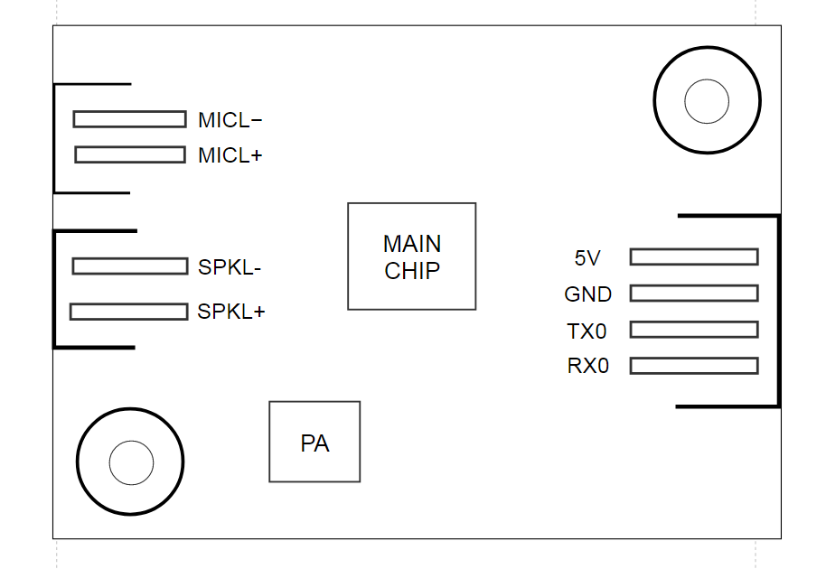
As shown in Figure 4, the voice recognition module is single-sided mounted. The main ICs include the CI1312/CI1303 voice recognition chip and a power amplifier. Sound is input from a single microphone, recognized by the voice IC, and sent to the amplifier to drive the speaker. The amplifier’s maximum output power is 1.5 W @ 8 Ω and 2 W @ 4 Ω.
Module Dimensions
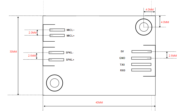
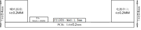
As shown in Figure 5, the module is rectangular with dimensions of 30 ± 0.3 mm × 40 ± 0.15 mm. The PCB thickness is 1.6 ± 0.2 mm, and the module height is 7.6 ± 0.4 mm. Users can design their mechanical structure based on these dimensions.
Hardware Interface Definition
This module provides the following functional interfaces:
- Two-wire single-microphone interface using a 2.0 mm pitch female connector. To ensure good recognition performance, use a microphone with sensitivity −32 ± 3 dB and SNR ≥ 65 dB. Click ☞Reference Microphone Devices for more information.
- Two-wire single-speaker interface using a 2.5 mm pitch female connector. For better playback, it is recommended to use a speaker with an enclosure. Click ☞Reference Speaker Devices for more information.
- Four-wire power and UART interface using a 2.5 mm pitch female connector. Refer to Figure 6 for pin order. The UART pins in this interface can be configured as GPIOs in addition to serial communication.
Descriptions of all external pins are shown in Table 2:
| Pin No. | Pin Name | I/O Type | IO Drive Capability | IO Default State at Power-on | Function Definition |
|---|---|---|---|---|---|
| 1 | 5V | P | - | - | 5V power |
| 2 | GND | P | - | - | Ground |
| 3 | UART_TX | IO, T+U | 4mA | IN, T+U | 1.UART0_TX 2.PB5 |
| 4 | UART_RX | IO, T+U | 4mA | IN, T+U | 1.UART0_RX 2.PB6 |
| 5 | MICL- | - | - | - | Microphone negative |
| 6 | MICL+ | - | - | - | Microphone positive |
| 7 | SKPL- | - | - | - | Speaker output |
| 8 | SKPL+ | - | - | - | Speaker output |
Descriptions of some symbols in the table above are as follows:
I input
O output
IO bidirectional
P power or ground
T+D tristate plus pull-down
T+U tristate plus pull-up
OUT power-on defaults to output mode
IN power-on defaults to input mode
Electrical Characteristics
| Parameter | Condition | Min | Typ | Max | Unit | Remark |
|---|---|---|---|---|---|---|
| Module supply voltage | / | 3.6 | 5 | 5.5 | V | NOTE1 |
| Module current during playback (normal volume) | 4Ω 3W speaker | / | 70 | / | mA | NOTE2 |
| Module operating current | / | / | 40 | / | mA | NOTE3 |
| Listening current in quiet environment | 5V supply | / | 35 | / | mA | / |
| Chip IO interface voltage | / | 3 | 3.3 | 3.6 | V | / |
| Module UART interface voltage | / | 4.5 | 5 | 5.5 | V | / |
NOTE1: 5 V is the typical supply voltage for the module. Input above 5.5 V may damage the module.
NOTE2: The maximum current during playback can reach 250 mA. Following the 2× margin principle, a 500 mA power supply capability should be provided.
NOTE3: The typical value is measured in mute state. The maximum value is measured during active recognition and playback.
Temperature and Humidity Parameters
The temperature and humidity parameters of CI-D1XGS08J are shown in Table 4.
| Parameter | Min | Typ | Max | Unit | Remark |
|---|---|---|---|---|---|
| Operating ambient temperature | -40 | 25 | 85 | °C | / |
| Storage ambient temperature | -40 | 25 | 100 | °C | / |
| Storage humidity | 0% | / | 5% | RH | / |
Module Application
Power-Up and Startup
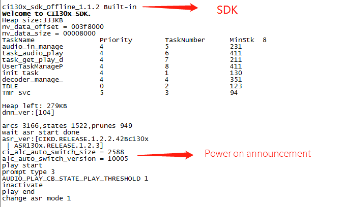
When using this module, connect the speaker and microphone, and input 5 V power through the power connector. After power-on, the module will start, and the speaker will play a prompt tone if startup is normal. Meanwhile, UART prints will appear. You can connect the UART to a computer using a USB-to-UART tool and view the prints in a serial terminal to confirm successful startup, as shown in Figure 7. Note that the module’s UART is a 5 V logic level high-speed serial port; no level shifting is required when interfacing with 5 V systems.
The on-board power amplifier is powered by 5 V. The 5 V supply should provide a rated current of 500 mA, with stable output and ripple within 30 mV.
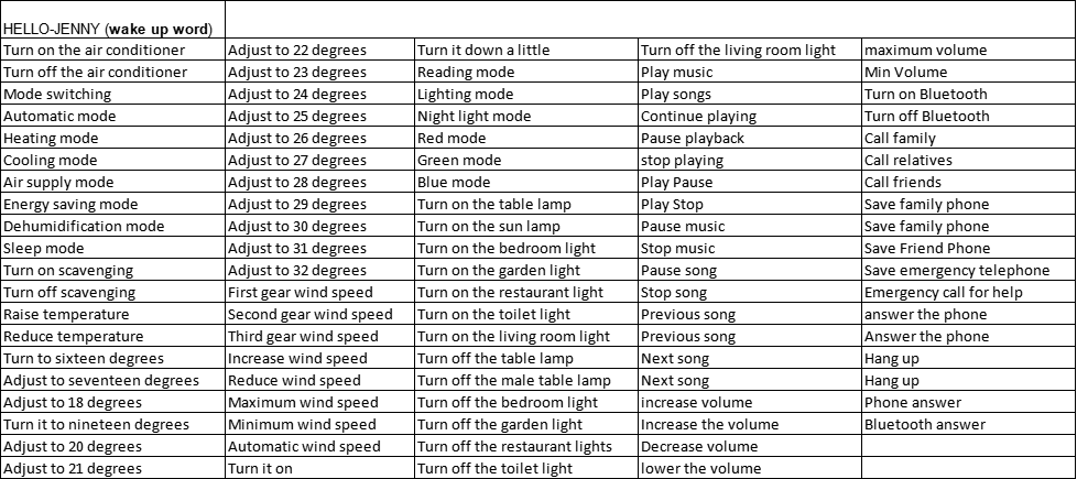
Default Command Set
For mass production, user-specified command-word firmware is normally programmed before shipment. If not specified, the module includes default firmware with a default command set for user testing, as shown below:
Default UART Communication Protocol
The default firmware supports a UART communication protocol for communication with a host computer. The protocol is extensible, with the following features:
- Complete transfer packet including header/footer, length, checksum, message type, and message sequence number.
- Supports variable-length commands for convenient expansion.
- Message types: command, notification, response.
- Command messages are configurable and require ACK; notification messages have no ACK.
- Message format is identical to the bootloader upgrade, differentiated by the header.
- Default baud rate: 9600.
- Note: Only UART0 is reserved on the module, and UART0 is the default print interface. To use UART0 for the above protocol, code modifications are required. Refer to the UART protocol section of ☞CI13XX Series Chip SDK.
- Supported commands include querying protocol version, querying system version, setting volume (levels defined in user_config.h), playing local audio, reset, etc. The specific protocol format is shown below:
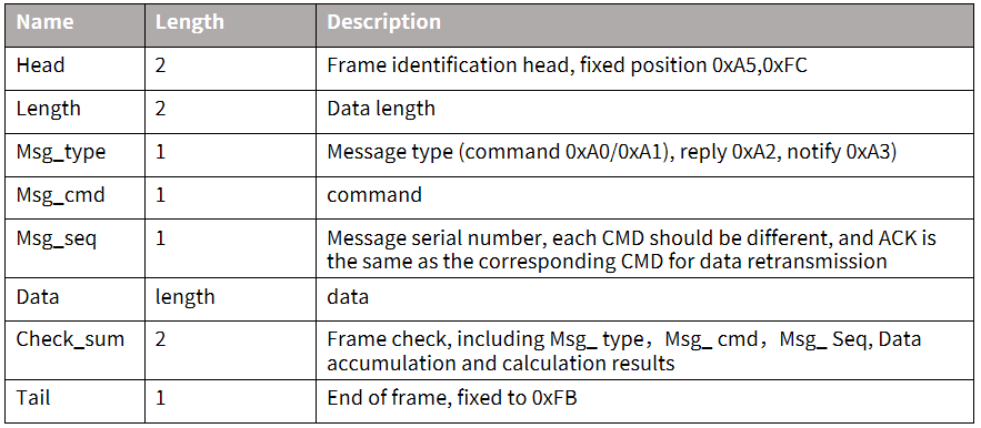
Example 1:
A5 FC 07 00 A0 91 18 01 55 E0 01 00 00 1B 9B 02 FB is parsed as follows:
A5 FC: header
07 00: valid data is 7 bytes
A0: this is command-word information
91: command number 0x91 (command-word data)
18: packet serial number; this is the 0x08th data sent by this UART, incrementing continuously
01 55 E0 01 00 00: semantic ID, UNIQUE
1B: command-word threshold
9B 02: checksum
FB: end byte
Note: If only the command word and threshold are needed, focus on the 7 valid data bytes in blue.
Example 2:
A5 FC 02 00 A3 9A 17 00 B1 05 02 FB is parsed as follows:
A5 FC: header
02 00: valid data is 2 bytes
A3: notification data
9A: command number 0x9A (voice module content changed)
17: this is the 0x07th data sent by this UART, incrementing continuously
00 B1: valid data (indicates entering wake state)
05 02: checksum
FB: end byte
Note: This is notification data; use it as needed.
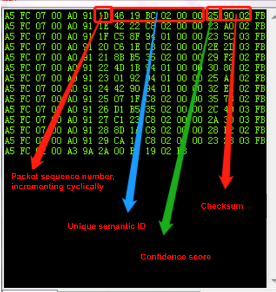
For further message parsing information, refer to the UART protocol section of ☞CI13XX Series Chip SDK. A reference screenshot is shown below:
Software Development
The default firmware on the module is mainly for initial evaluation. For software development, please register and log in to the AI platform (https://aiplatform.chipintelli.com) for rapid voice firmware development. Meanwhile, you can download the SDK and related hardware materials in the “Development Materials” section of the AI platform. For first-time users of the AI platform, it is recommended to start with the Getting Started Guide to understand the development process, and also refer to the documentation center’s Video Tutorials for more solutions and SDK development introductions.
- SDK package download
- Model generation(language model + acoustic model)
- Text-to-speech (TTS)
- Associate command-word table with audio files
- Firmware packaging
For detailed development procedures, click ☞CI13XX Series Chip SDK.
Firmware Programming
Preparation Before Programming
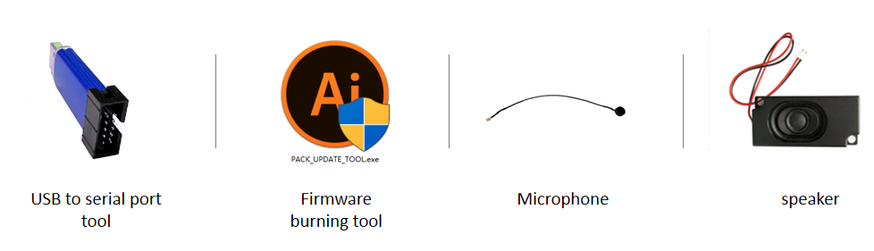
Before programming the module, prepare the following items:
- The module to be programmed
- USB-to-UART tool
- Firmware programming tool (pack_update_tool.exe)
- Firmware file (*.bin)
- 2.0 mm pitch microphone
- 2.5 mm pitch speaker
- Several Dupont wires
Hardware Connection and Programming
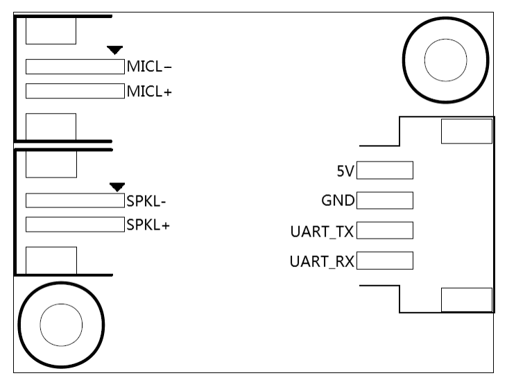
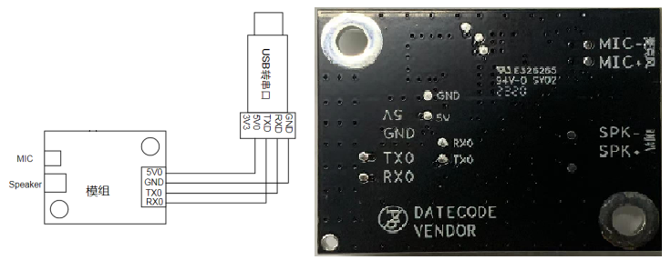
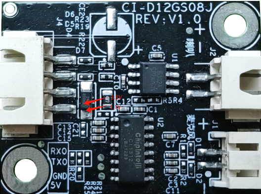
Using the USB-to-UART tool shown above as an example, before programming, connect the tool’s power, ground, and TX/RX pins to the corresponding module pins (note that the tool’s RXD and TXD correspond to the module’s UART0_TX and UART0_RX). The programming wiring diagram and the module’s back-side silkscreen are shown below.
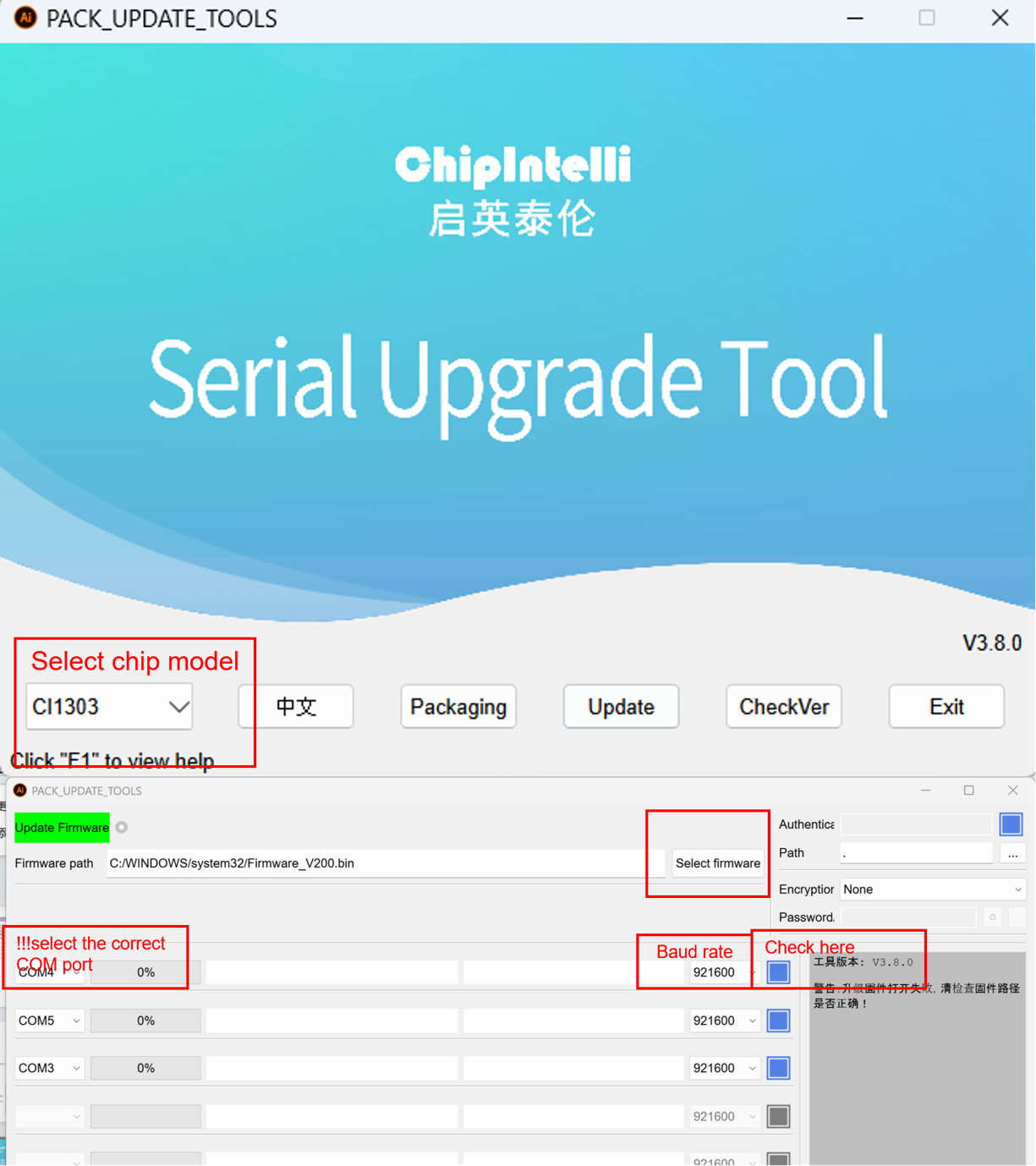
Open the firmware programming tool (located in CI130X_SDK\tools as PACK_UPDATE_TOOL.exe). Select the corresponding chip model, click the firmware update button, select the prepared firmware file, and find the COM port assigned to the USB-to-UART tool. After preparations are complete, momentarily power the chip to enter programming mode and download the firmware. If the USB-to-UART tool is not recognized by the computer, install the appropriate driver.
Functional Testing After Programming
After successful firmware programming, it is recommended to perform functional testing to verify success. Connect a microphone and speaker to the module under test, power it on, and check whether power-on audio plays normally. Then test the wake word and command words to confirm wake and recognition. If everything works, the module functions normally and programming has succeeded; otherwise, programming failed and further investigation is required.
Possible Issues and Solutions During Use
This section lists potential issues during use and corresponding solutions.
- The module cannot be programmed/updated.
If this occurs, check the following:
- Connect TX, RX, and GND first, then select the corresponding COM port in the programming tool (Figure 13, item 4), then supply 5 V power.
- Verify UART pin connections, ensure TX and RX are not swapped, confirm the USB-to-UART driver on the PC is installed correctly, and that the correct COM port is selected in the programming tool.
- If the above checks are correct yet programming still fails, measure the module’s 5 V, 3.3 V, and 1.1 V rails with a multimeter. Refer to the test points below. If a voltage or crystal issue is found, consider a hardware fault; replace or repair the module hardware. If all checks pass, contact our technical support team.
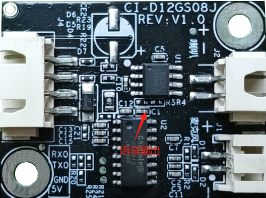
- After programming, there is no playback on power-up.
If this occurs, check the following:
- Confirm the programmed firmware matches the board.
- Confirm the speaker is properly connected and power is normal.
Use an oscilloscope to measure the voice output test point of the main chip. If there is no output, check whether the firmware is correct. If there is output, check the power amplifier device on the module for soldering anomalies; replace and retest if necessary. The measurement point is shown below. If all checks pass, contact our technical support.
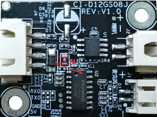
- After programming, power-on playback exists but command words are not recognized:
- Check whether the microphone and connector are properly connected.
- Verify the microphone polarity matches the board markings and is not reversed.
- Use a multimeter to measure whether the MICBIAS pin of the main chip is around 2.8 V, and use an oscilloscope to check for an input voice waveform at the microphone pin (set vertical scale to 100 mV/div). If the signal is normal, consider firmware issues; if abnormal, inspect hardware for physical damage. The measurement point is shown below. If all checks pass, contact our technical support.
Other Application Notes
Because the CI1312/CI1303 chips have relatively high ESD levels and the module is designed for easy expansion, ESD devices are only designed at the microphone location on the module. For products with stringent ESD requirements, additional ESD devices can be added. It is recommended that users wear anti-static wrist straps and gloves/finger cots during inspection and soldering. Reserve ESD protection components at the corresponding baseboard connector locations to ensure product quality and reliability.
During use, ensure that the microphone, speaker, and power/UART connections are correct, and prevent short circuits at the back-side test points.
Note that the module’s UART uses 5 V logic levels. Please use a 5 V-level UART for communication. You can use a USB-to-UART tool to debug your software; add UART print statements in the appropriate places in the SDK, compile to generate firmware, program it, and then perform debugging and verification.
Production Guide, Storage, and Packaging/Ordering Information
Production Guide
This module uses integrated terminal connectors, making production simple and convenient. Insert the microphone, speaker, and power/communication terminals into their corresponding connectors to use. The board interfaces are fool-proof, preventing mis-insertion among the three terminals. During insertion, wear anti-static gloves and wrist straps, and apply appropriate force to ensure connectors are fully seated. Open the vacuum ESD bag just before assembly.
Storage Conditions
The module is vacuum-packaged, so storage requirements are not stringent. Store in a non-condensing atmosphere at < 40℃ / 90% RH. The module’s Moisture Sensitivity Level (MSL) is 3; after the vacuum bag is opened or leaks, handle according to MSL 3 requirements.
Packaging and Ordering Information
| Product Model | Packaging Method | Modules per Tray | Modules per Pack | Modules per Carton |
|---|---|---|---|---|
| CI-D11GS08J CI-D12GS08J |
Tray + ESD bag + Carton | 40 pcs | 10 trays, total 400 pcs | 3 bags, total 1200 pcs |
Purchasing and Technical Support
If you want to purchase product samples, click ☞Sample Purchase. You can also click ☞Samples and Bulk Purchase for more information.
If you need technical support, please log in to the ☞AI platform.