CI-D06GT01J Module Datasheet
Module Introduction
Overview
This module is a general-purpose, portable, low-power, high-performance voice recognition module developed for low-cost offline voice applications. The model is CI-D06GT01J, with CI1306 as the main chip, supporting recognition of up to 500 offline command words.
This module has the following features:
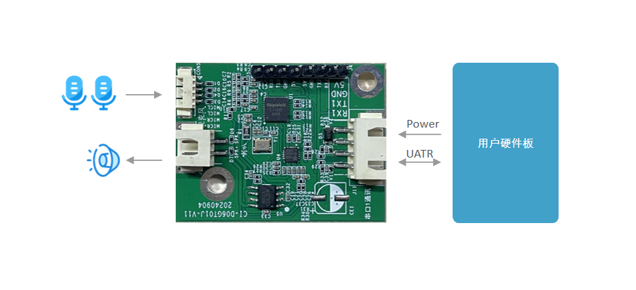
- Compact size of 34 × 45 mm; operating voltage 3.6 V–5 V. The board integrates a power amplifier and an ADC chip, with one dual-microphone interface, one speaker interface, one 5 V power input, and three UART interfaces. Typically powered by the product main board’s 5 V supply with UART communication; simply add microphone and speaker connectors on the main board. The module includes two 4 mm screw holes for flexible and convenient mounting.
- Low power consumption, suitable for products with energy-efficiency requirements and battery-powered products.
- High reliability with industrial-grade components.
- High performance. The dual-microphone + AEC design achieves high recognition accuracy, long-distance recognition, dual-microphone noise reduction, and dual-microphone echo cancellation.
| Module | Up to 500 local command words |
|---|---|
| Dual-mic offline voice module with connectors | CI-D06GT01J |
Main Chip Introduction
CI1306 is an AI chip specifically designed for voice processing. It supports local voice recognition and multiple global languages including Chinese, English, and Japanese. It can be widely used in home appliances, lighting, toys, wearables, industrial, and automotive products to enable voice interaction, control, and various intelligent voice solutions.
CI1306 integrates chipintelli’s self-developed BNPU V3 neural network processor and a CPU core; system frequency up to 240 MHz; up to 640 KByte on-chip SRAM; integrated PMU and RC oscillator; dual-channel high-performance, low-power Audio Codec; and multiple peripherals including UART, I2C, I2S, PWM, GPIO, and PDM. Only a few external components are required to realize various intelligent voice hardware solutions with excellent cost performance.
For more detailed information about CI1306, click the link below:
Module Application Scenarios
This module can be used as a voice recognition front-end combined with the customer’s main control board, or as a stand-alone main control module for lighting, toys, and other solutions. Connect an external microphone and speaker, and supply power via an external 5 V source.
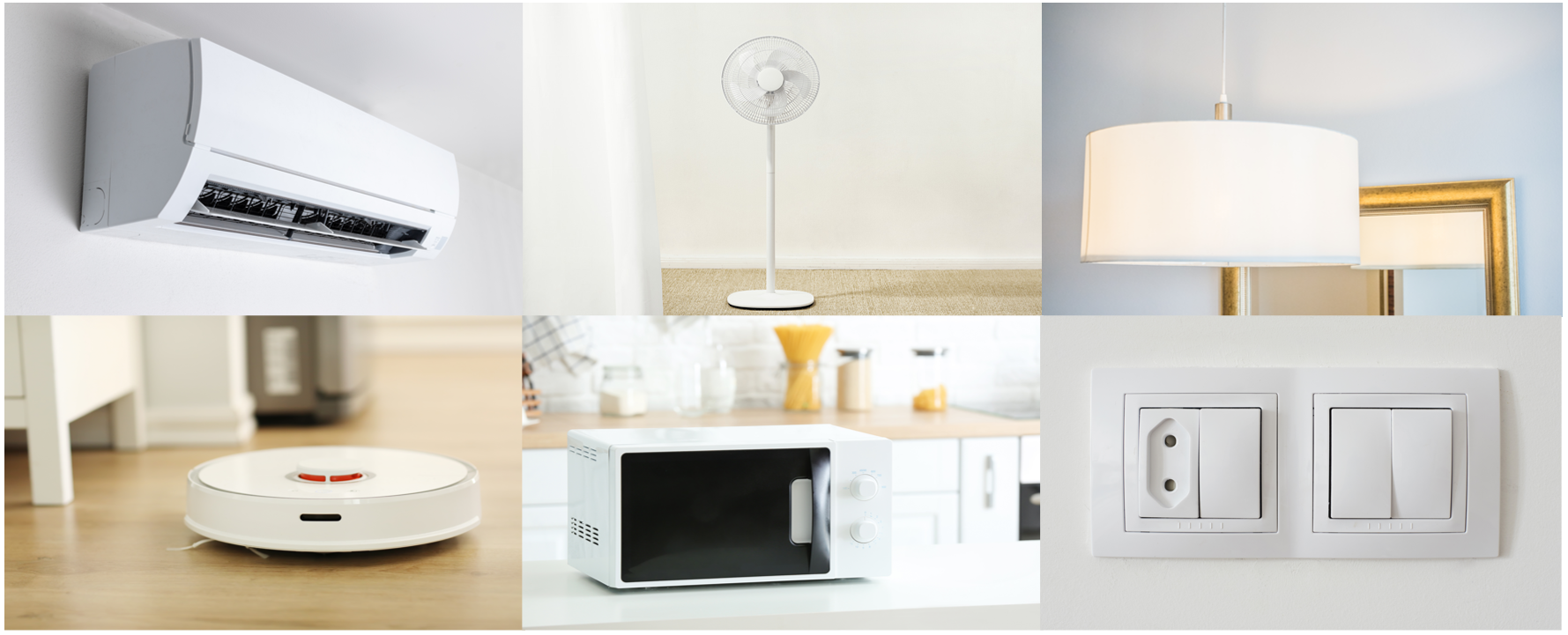
The CI-D06GT01J module supports up to 500 offline command words and can be applied to smart air conditioners, smart fans, heating tables, clothes dryers, small appliances, toys, lighting, and more.
Module Specifications
Module Photos
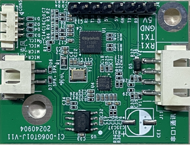
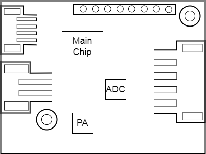
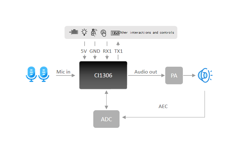
As shown in Figure 4, the voice recognition module is single-sided mounted. The main ICs include the voice recognition chip (CI1306), a dedicated ADC chip (ES7243e), and a power amplifier. Voice is input from dual microphones, recognized by the voice chip, and then sent to the power amplifier to drive the speaker (maximum output power of 1.5 W @ 8 Ω and 2 W @ 4 Ω). A dedicated on-board ADC chip suppresses the echo signal reaching the microphone from the speaker in real time to improve recognition of the target voice.
Module Dimensions
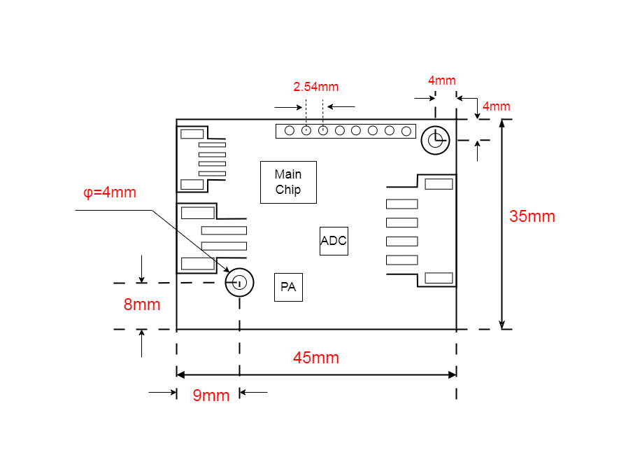
As shown in Figure 5, users can design their mechanical structure based on these dimensions.
Hardware Interface Definition
This module provides the following functional interfaces:
- Four-wire dual-microphone interface using a 1.25 mm pitch female connector. To ensure good recognition performance, it is recommended to use microphones with sensitivity −32 ± 3 dB and SNR ≥ 65 dB. Click ☞Reference Microphone Devices for more information.
- Two-wire single-speaker interface using a 2.5 mm pitch female connector. For better playback, it is recommended to use a speaker with an enclosure. Click ☞Reference Speaker Devices for more information.
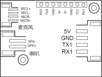
- Four-wire power and UART1 interface using a 2.5 mm pitch female connector. Refer to Figure 6 for pin order. The UART1 pins can also be configured as GPIOs in addition to serial communication.
- 8-pin header interface: UART0 is reserved for firmware updates; UART2 can be used as a communication interface. The UART pins can also be configured as GPIOs.
Descriptions of all external pins are shown in Table 2:
| Pin Name | Type | IO 5V Tolerance | IO Default State at Power-on | IO Drive Strength | Function Definition |
|---|---|---|---|---|---|
| 5V | P | - | - | - | 5 V power |
| GND | P | - | - | - | Ground |
| TX0 | IO | √ | IN, T+U | 4 mA | 1. GPIO PB5 2.UART0_TX 3.I2C_SDA 4.PWM Channel 1 |
| RX0 | IO | √ | IN, T+U | 4 mA | 1. GPIO PB6 2.UART0_RX 3.I2C_SCL 4.PWM Channel 2 |
| TX1 | IO | √ | IN, T+U | 4 mA | 1. GPIO PB7 2.UART1_TX 3.I2C_SDA 4.PWM Channel 3 |
| RX1 | IO | √ | IN, T+U | 4 mA | 1. GPIO PC0 2.UART1_RX 3.I2C_SCL 4.PWM Channel 4 |
| TX2 | IO | √ | IN, T+D | 4 mA | 1. GPIO PB1 2.PWM Channel 2 3.UART2_TX |
| RX2 | IO | √ | IN, T+D | 4 mA | 1. GPIO PB2 2.PWM Channel 3 3.UART2_RX |
| MICL+ | - | - | - | - | Left microphone positive |
| MICL- | - | - | - | - | Left microphone negative |
| MICR+ | - | - | - | - | Right microphone positive |
| MICR- | - | - | - | - | Right microphone negative |
| SKP- | - | - | - | - | Speaker output |
| SKP+ | - | - | - | - | Speaker output |
Descriptions of the symbols in the table above are as follows:
I input
O output
IO bidirectional
P power or ground
T+D tristate plus pull-down
T+U tristate plus pull-up
OUT power-on defaults to output mode
Electrical Characteristics
| Parameter | Condition | Min | Typ | Max | Unit | Remark |
|---|---|---|---|---|---|---|
| Module supply voltage | / | 3.6 | 5 | 5.5 | V | NOTE1 |
| Module current during playback (normal volume) | 8Ω 2W speaker | / | 104 | / | mA | NOTE2 |
| Module operating current | / | / | 44 | / | mA | NOTE3 |
| Listening current in quiet environment | 5V supply | / | 44 | / | mA | / |
| Chip IO interface voltage | / | 3 | 3.3 | 3.6 | V | / |
| Module UART1 interface voltage | / | 4.5 | 5 | 5.5 | V | / |
NOTE1: 5 V is the typical supply voltage for the module. Input voltage above 5.5 V may damage the module.
NOTE2: The maximum current during playback can reach 250 mA. Following the 2× margin principle, a 500 mA power supply capability should be provided.
NOTE3: The typical value is measured in mute state. The maximum value is measured during recognition and playback.
Temperature and Humidity Parameters
Parameter | Min | Typ | Max | Unit | Remark :–: | :–: | :–: | :–: | :–: | :–: | :–: Operating ambient temperature | -40 | 25 | 85 | °C | / Storage ambient temperature | -40 | 25 | 100 | °C | / Storage humidity | 0% | / | 5% | RH | /
Module Application
Power-Up and Startup
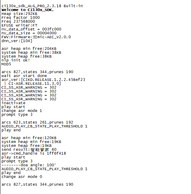
When using this module, connect the speaker and microphone, and input a 5 V power supply to the module via the power connector; the module will start after power-on. If startup is normal, the speaker will play a prompt tone. Meanwhile, UART0 prints will be output. You can connect UART0 to a PC using a USB-to-UART tool and view the prints in a serial terminal; output as shown in Figure 7 indicates normal startup. The on-board power amplifier is powered by 5 V. The 5 V supply should provide a rated current of 500 mA with stable output and ripple within 30 mV.
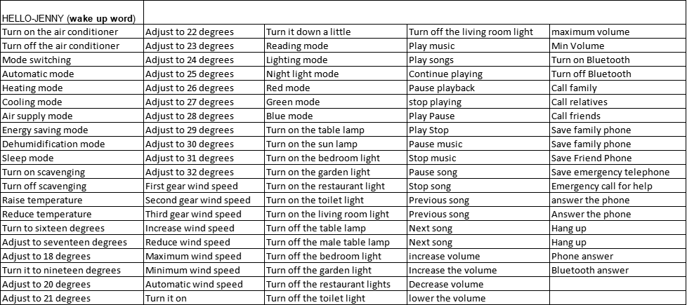
Default Command Set
For mass production, user-specified command-word firmware is usually programmed before shipment. If not specified, the module ships with default firmware containing a default command set for testing, as shown below:
Default UART Communication Protocol
Modules programmed with the general-purpose firmware support UART communication for interfacing with a host or target system. The UART protocol is extensible and has the following features:
- Complete transfer packet including header/footer, length, checksum, message type, and message sequence number.
- Supports variable-length commands, enabling easy extension.
- Message types include command, notification, and response.
- Command messages are configurable and require ACK; notification messages have no ACK.
- Message format is identical to the bootloader upgrade, distinguished by the header.
- Default baud rate: 9600.
- Note: Only UART0 is reserved on the module, and UART0 is the default print output interface. To use UART0 for the above protocol, code changes are required. Refer to the UART protocol section of ☞CI13XX Series Chip SDK.
- Supported commands include: query protocol version, query system version, set volume (levels defined in user_config.h), play local broadcast audio, reset, etc. The specific protocol format is shown below:

Example 1:
A5 FC 07 00 A0 91 18 01 55 E0 01 00 00 1B 9B 02 FB is parsed as follows:
A5 FC: header
07 00: valid data is 7 bytes
A0: command-word information
91: command number 0x91 (command-word data)
18: packet sequence number; this is the 0x08th data sent by this UART, incrementing continuously
01 55 E0 01 00 00: semantic ID, UNIQUE
1B: command-word threshold
9B 02: checksum
FB: end byte
Note: If only the command word and threshold are of interest, focus on the 7 valid data bytes in blue.
Example 2:
A5 FC 02 00 A3 9A 17 00 B1 05 02 FB is parsed as follows:
A5 FC: header
02 00: valid data is 2 bytes
A3: notification data
9A: command number 0x9A (voice module content changed)
17: this is the 0x07th data sent by this UART, incrementing continuously
00 B1: valid data (indicates entering wake state)
05 02: checksum
FB: end byte
Note: This is notification data; use it as needed.
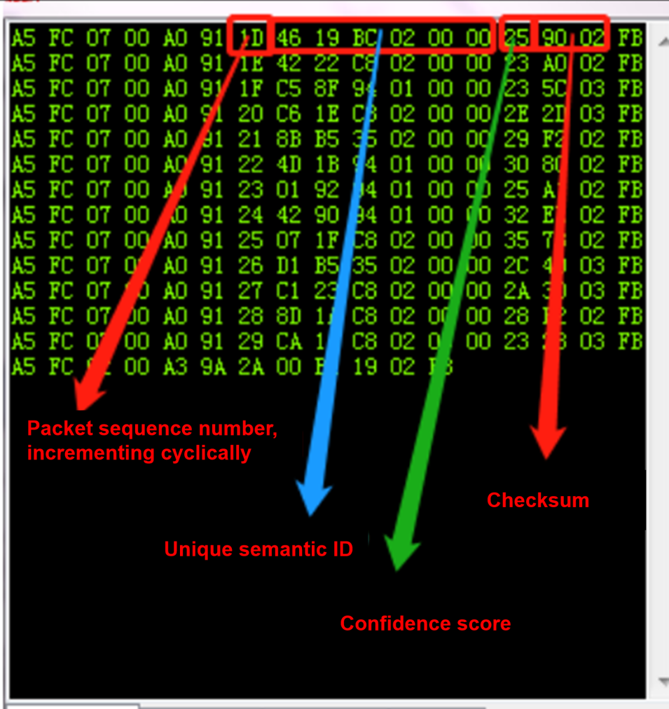
For more details on message parsing, refer to the UART protocol section of ☞CI13XX Series Chip SDK. A reference screenshot is shown below:
Software Development
The default firmware on the module is mainly for initial evaluation. For software development, please register and log in to the AI platform (https://aiplatform.chipintelli.com) for rapid voice firmware development. Meanwhile, you can download the SDK and related hardware materials in the “Development Materials” section of the AI platform. For first-time users of the AI platform, it is recommended to read the Getting Started Guide to understand the development process, and refer to the documentation center’s Video Tutorials for more solutions and SDK development introductions.
The software development process mainly includes the following steps:
- SDK package download
- Model generation(language model + acoustic model)
- Text-to-speech (TTS)
- Associate command-word table with audio files
- Firmware packaging
For detailed development procedures, click ☞CI13 Series Chip SDK.
Firmware Programming
Preparation Before Programming
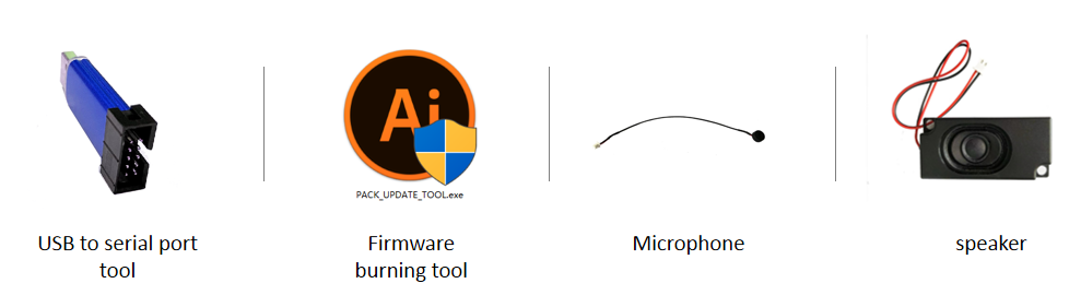
Before programming the module, prepare the following items:
- The module to be programmed
- USB-to-UART tool
- Firmware programming tool (pack_update_tool.exe)
- Firmware file (*.bin)
- 1.25 mm pitch 4P dual microphone
- 2.54 mm pitch speaker
- Several Dupont wires
Hardware Connection and Programming
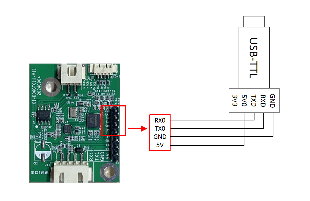
Using the USB-to-UART tool shown above as an example, before programming, connect the tool’s power, ground, and TX/RX pins to the corresponding module pins (note that the tool’s RXD and TXD correspond to the module’s TX0 and RX0). The connection method is shown below.
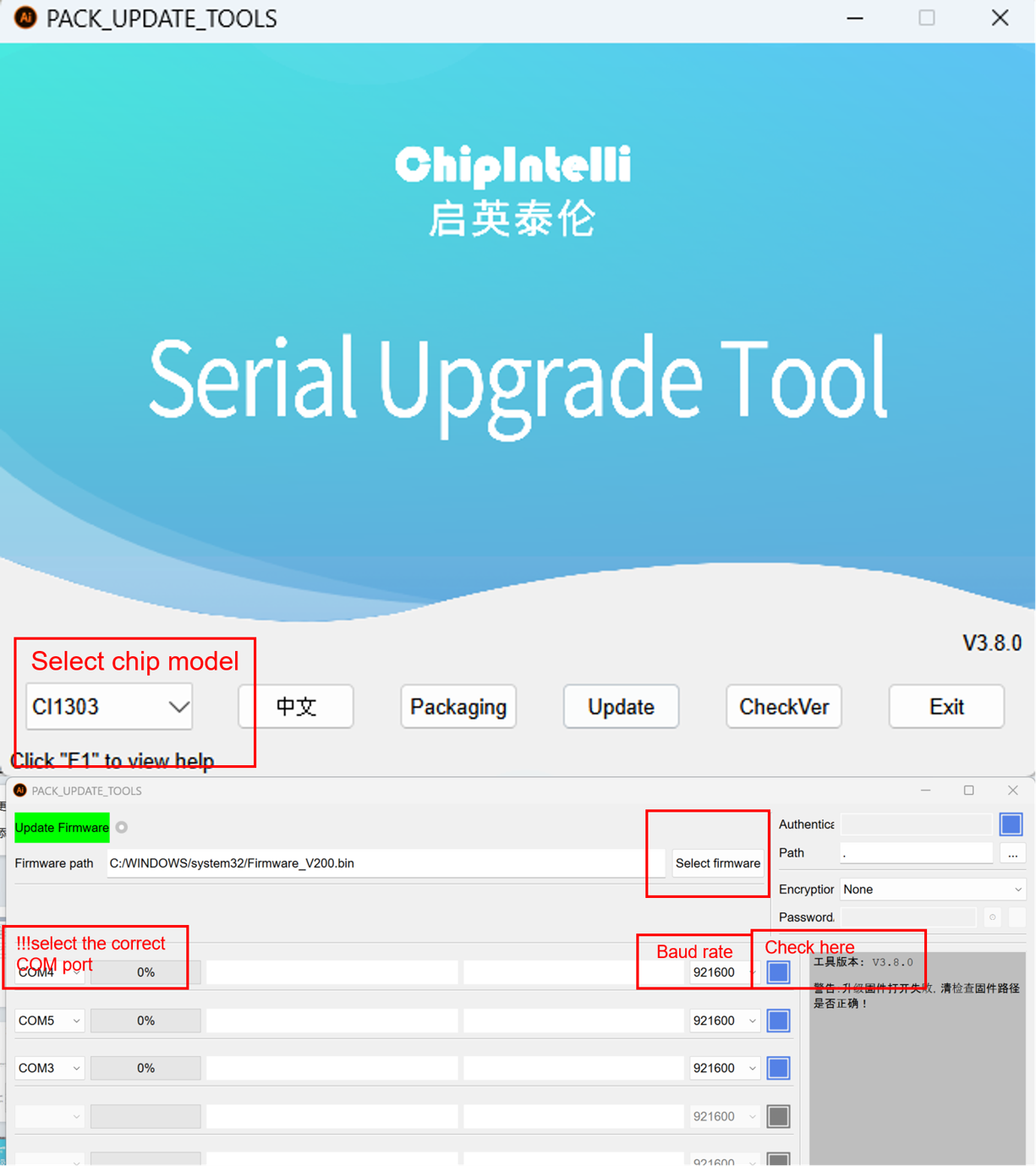
Open the firmware programming tool (found in CI130X_SDK\tools as PACK_UPDATE_TOOL.exe). Select the corresponding chip model, click the firmware update button, select the prepared firmware file, and confirm the COM port assigned to the USB-to-UART tool. After powering the module, it will enter firmware update mode and begin downloading the firmware. If the computer cannot recognize the USB-to-UART tool, please install the appropriate driver first.

Functional Testing After Programming
After firmware programming is completed, it is recommended to perform functional testing to verify success. Before testing, connect a microphone and speaker to the module under test, power it on to confirm boot audio playback, and test wake word and command words for wakeup and recognition. If all are normal, the module is functioning properly and programming succeeded; otherwise, programming failed and further investigation is needed.
Possible Issues and Solutions During Use
This section lists some issues that may be encountered during use and corresponding solutions.
- The module cannot be programmed/updated.
If this occurs, check the following:
- Ensure TX0, RX0, and GND are connected first, then select the corresponding COM port in the programming tool, and finally apply 5 V power.
- Verify UART pin connections; ensure TX and RX are not swapped; confirm the PC-side USB-to-UART driver is installed correctly; and confirm the correct COM port is selected in the programming tool.
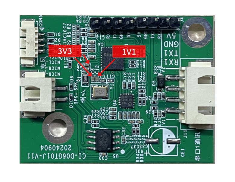
- If the above checks are correct but programming still fails, use a multimeter to measure whether the 5 V, 3.3 V, and 1.1 V rails are correct. Refer to the test points in the figure below. If voltage issues are found, consider a hardware fault; replace the module or repair the hardware. If all checks are normal, contact our technical support team.
- After programming, there is no playback on power-up.
If this occurs, check the following:
- Confirm the programmed firmware matches the board.
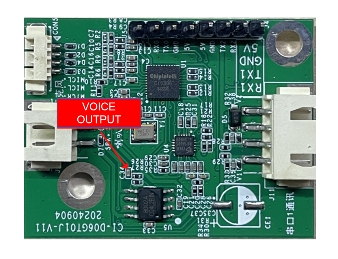
- Confirm the speaker is properly connected and power is normal. Use an oscilloscope to measure the voice output test point of the main chip. If there is no output, check whether the firmware is correct. If there is output, check whether the power amplifier on the module has soldering anomalies; replace it if necessary and test again. The measurement point is shown below. If all checks are normal, contact our technical support team.
- After programming, power-on playback exists but command words are not recognized:
- Check whether the microphone connections are intact.
- Verify the microphone polarity matches the markings on the module and is not reversed.
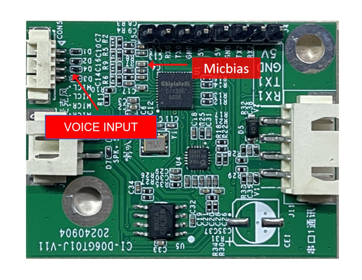
- Use a multimeter to measure whether the MICBIAS pin of the main chip is around 2.8 V, and use an oscilloscope to check whether there is an input voice waveform at the microphone input pin (set 100 mV per division). If the signal is normal, consider firmware issues; if abnormal, inspect the board hardware for physical damage. The measurement point is shown below. If all checks are normal, contact our technical support team.
Other Application Notes
-
The module design adopts a high-reliability scheme. ESD devices are placed at the microphone, speaker, and UART1 connector locations to meet the needs of products with high ESD requirements. It is still recommended to wear anti-static wrist straps and gloves/finger cots during inspection and soldering to ensure product quality and reliability.
-
During use, ensure that microphone, speaker, and power/UART connections are correct.
-
You can use a USB-to-UART tool to debug your software. Add UART print statements at appropriate locations in the SDK, compile to generate the firmware, program it, and then perform debugging and verification.
Production Guide, Storage, and Packaging/Ordering Information
Production Guide
Thanks to the integrated terminal connectors, production is simple and convenient. Insert the microphone, speaker, and power/communication terminal accessories into their respective connectors to use. The board uses fool-proof connectors, preventing mis-insertion between the three terminals. During insertion, wear anti-static gloves and wrist straps, and apply appropriate force to ensure connectors are fully seated. Open the vacuum ESD packaging bag before starting assembly.
Storage Guide
The module is vacuum-packed and therefore has modest storage requirements. Store in a non-condensing atmosphere at < 40℃ / 90% RH. The module’s Moisture Sensitivity Level (MSL) is 3; after the vacuum bag is opened or leaks, manage according to MSL 3.
Packaging and Ordering Information
| Product Model | Packaging Method | Modules per Tray | Modules per Pack | Modules per Carton |
|---|---|---|---|---|
| CI-D06GT01J | Tray + ESD bag + Carton | 40 pcs | 10 trays, total 400 pcs | 3 bags, total 1200 pcs |
Purchasing and Technical Support
If you want to purchase product samples, click ☞Sample Purchase. You can also click ☞Samples and Bulk Purchase for more information.
If you need technical support, please log in to the ☞AI platform.