Voice Recognition Performance Optimization
1 Overview and Background
This document is primarily intended for developers with software development and hardware debugging capabilities who are already familiar with the Chipintelli Voice SDK and solution development process. It provides guidance for debugging and optimizing recognition performance.
2 Troubleshooting Recognition Performance
Voice recognition performance is a comprehensive result influenced by both recognition algorithms (similar to the human brain) and hardware structure characteristics (similar to human ears). When recognition performance is suboptimal, we recommend first using comparative methods to check for environmental influences before proceeding with software optimization. The following process can be followed for troubleshooting.
2.1 Microphone Pickup Performance Analysis via Audio Recording
The quality of the audio signal input from the microphone directly affects recognition performance. Therefore, it’s essential to record and analyze the microphone’s input audio and circuit to determine if the hardware circuit, structure, and microphone components meet requirements. Audio recording can also help identify microphone circuit-related recognition issues. For details, refer to: Audio Capture Board User Guide for noise floor recording. Observe the captured audio waveform for any abnormalities, such as clipping, high noise floor, or extremely low speech amplitude at normal volume levels. Refer to the optimization directions below for improvement.
2.2 Hardware Optimization
2.2.1 Ensure microphone parameters are correct, polarity is correct, there are no poor connections, and the sound inlet is not blocked.
For microphones used with our voice chips, two key specifications must be met: sensitivity must be -32±3dB, and signal-to-noise ratio (SNR) must be ≥65dB. We recommend using our verified microphone design solutions. Refer to our Peripheral Device Compatibility List to select an appropriate microphone.
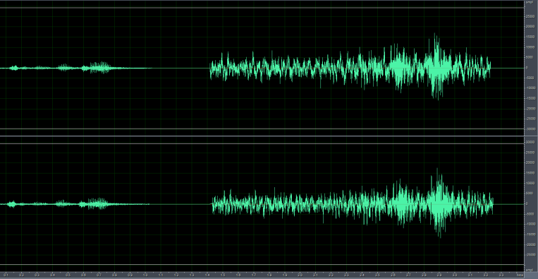
As shown in the figure below, the left signal shows the audio input when the microphone is reverse-connected, with significantly lower amplitude compared to the correctly connected microphone on the right.
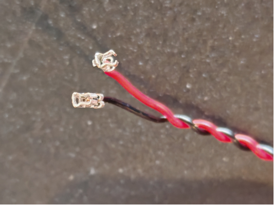
In the image below, an improperly sized microphone socket causes a poor connection with the terminal.
2.2.2 During complete device assembly, ensure microphone cables are kept away from 220V power lines and other high-voltage cables, and maintain distance from high-power components on the PCBA such as relays and transformers.
AC power can introduce power frequency interference, which may couple into the microphone signal, causing a “humming” sound (low-frequency noise). Additionally, if power cables are poorly insulated, high voltage may damage the microphone circuit when in close proximity, leading to signal abnormalities or even microphone failure. Some components may generate high-frequency transient noise during switching or operation, potentially causing electromagnetic interference or conducted interference with the microphone signal, leading to voice distortion or increased noise floor.
2.2.3 Ensure the microphone circuit design complies with specifications. Below are key design specifications that significantly impact recognition performance. For other design specifications, please refer to our hardware design documentation.
As shown below, the power supply ripple for the voice chip should be less than 300mV. Excessive power ripple can affect voice recognition performance. Adding TVS diodes and resistors can effectively suppress power surges and interference ripple.
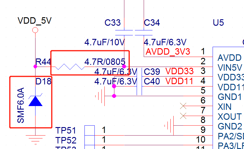
The voice chip has filter capacitor pins (VDD, AVDD, VDD33, VDD11) and a VCM pin, each requiring a 4.7μF capacitor. Place these capacitors as close as possible to the chip, with a distance <5mm between the capacitor and chip pin, and trace width ≥0.4mm. Add multiple ground vias near the ground side of each capacitor, with at least one ground via per capacitor.
Keep the ground return paths for VDD, AVDD, VDD33, and VDD11 as short as possible without unnecessary routing. The power ripple for AVDD, VDD33, and VDD11 should be ≤50mV. If the decoupling capacitors are too far from the chip pins, ripple may increase.
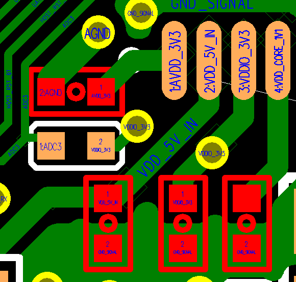
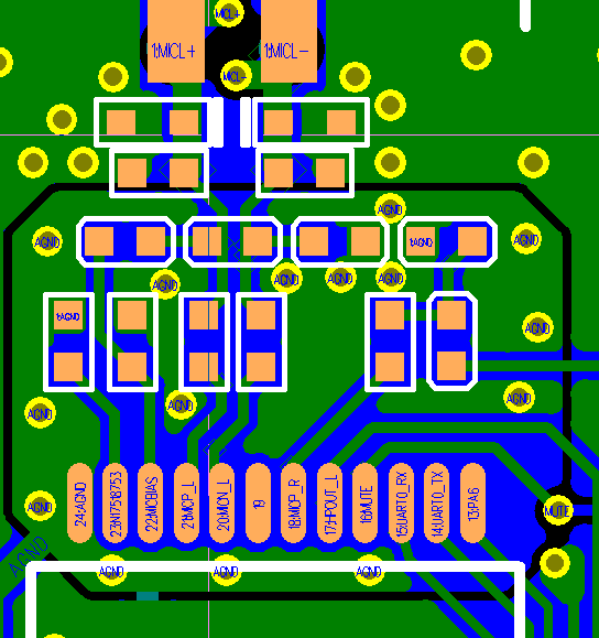
As shown below, place the RC components of the microphone circuit as close to the chip as possible (distance <5mm). Route MIC+ and MIC- in parallel, preferably without vias. Minimize the layout path between the microphone and voice chip, avoid routing on the bottom layer, ensure ground integrity, and use solid ground planes on both top and bottom layers. Add ground vias generously, with at least the voice processing section fully grounded.
2.3 Mechanical Optimization
After confirming the hardware is functioning correctly, if all command words show poor recognition performance, remove the microphone from the device housing and test it while mounted on the surface or directly on the bare board. If performance improves significantly, the mechanical structure may be causing the recognition issues and requires optimization. Additionally, check if the device’s mechanical noise is excessive. Noise levels above 75dB at the microphone can significantly impact recognition. Mechanical noise can be observed through audio recording, with amplitude ideally not exceeding 5000. If mechanical noise is too high, structural optimization is necessary. In the image below, the noise amplitude at the microphone structure is at maximum, requiring structural modifications.
For mechanical optimization, refer to Product Structure Design to optimize the device structure.
2.4 Software Optimization
After eliminating hardware and mechanical factors, consider software-based optimizations.
2.4.1 Poor Overall Command Word Recognition
First, determine the appropriate acoustic model based on the product’s usage scenario, as different acoustic models perform differently in various environments.
In the Chipintelli AI Platform → Language Model Development, select the appropriate parameters and application scenario to choose the corresponding acoustic model. For example, the model name “Chinese_Fan_Universal_pro4_V1_1.3M_V01374” contains the following information, indicating it’s suitable for Chinese fan products:
| Name | Description |
|---|---|
| Chinese | Supported language |
| Fan Universal | Intended application scenario (fans) |
| pro4 | Model type: Standard or Pro. Higher X in proX indicates better compression. Pro models with higher compression are recommended. |
| V1 | Version number. Always use the latest version when available. |
| 1.3M | Model size |
| V01374 | Model ID. Can be referred to as “1374 model” for communication purposes. |
| ----------------------------------- |
Second, use the platform’s automatic language model optimization feature during model development.
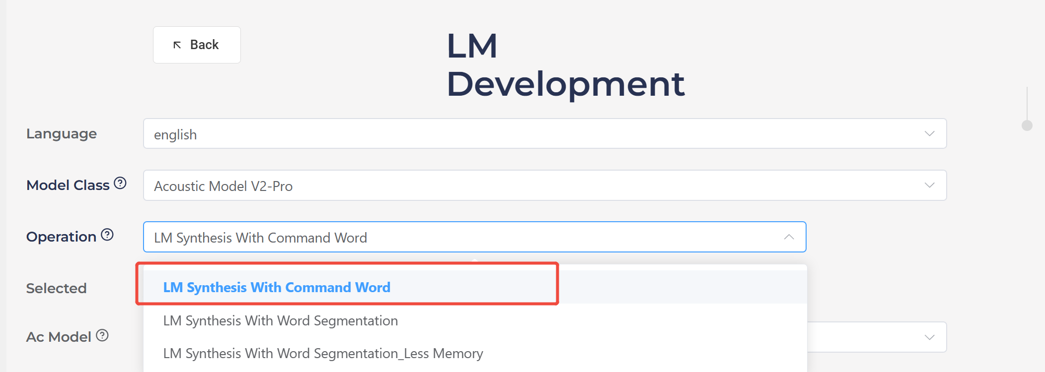
In the Chipintelli AI Platform → Language Model Development, select “LM Synthesis With Command Word” and enable the automatic optimization option. As shown below, Pro acoustic models generally achieve ideal recognition performance after platform optimization.
Finally, specific algorithms can be applied to optimize recognition performance.
- Change from Dynamic Gain to Fixed Gain
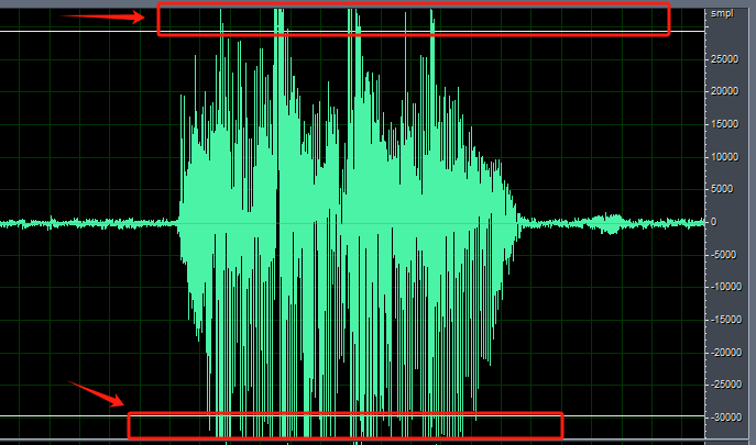
For products like massagers or helmets where the microphone is used at close range, the pickup may experience clipping (as indicated by the red arrow in the image below). In such cases, switching from dynamic gain to fixed gain can help. This approach is also effective when the microphone is close to steady noise sources like fans or range hoods.
The following explains several technical terms:
ALC (Automatic Level Control) automatically adjusts gain. When the speech signal amplitude is too small, it increases the gain to amplify the signal for better recognition. When the speech signal amplitude is too large, it reduces the gain to decrease the signal amplitude for proper recognition. The default gain upon power-up is 28.5dB, after which it varies automatically based on the environment.
Dynamic ALC dynamically controls the ALC on/off. When ALC adjustment amplifies the signal too much (since ALC only has a few gain steps, it might suddenly amplify the signal too much causing clipping), it will automatically turn off ALC and switch to fixed gain to reduce the signal amplitude, prevent clipping, and ensure basic recognition. When the external signal becomes smaller, it will automatically re-enable ALC. Since the gain changes automatically in different environments, it’s called dynamic gain.
Fixed gain means turning off both dynamic ALC and ALC, then setting the gain to a fixed value. The gain remains constant across different environments.
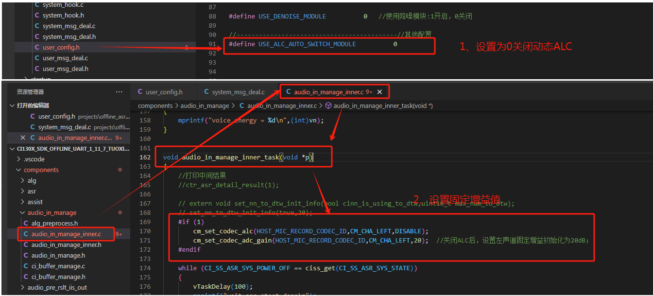
Fixed Gain Configuration for CI130X Single-Microphone Solution
To implement fixed gain in the CI130X single-microphone solution, first disable dynamic ALC, then add the following two lines of code at the beginning of the audio_in_manage_inner_task() function in audio_in_manage_inner.c:
cm_set_codec_alc(HOST_MIC_RECORD_CODEC_ID, CM_CHA_LEFT, DISABLE);
cm_set_codec_adc_gain(HOST_MIC_RECORD_CODEC_ID, CM_CHA_LEFT, 20); // After disabling ALC, set fixed gain to 20dB for left channel; gain range: -18dB to 28dB, recommended range: 15-28dB; increase toward 28dB for lower noise environments, decrease toward 15dB for noisier environments.
Fixed Gain Configuration for CI130X Dual-Microphone Solution
For dual-microphone solutions, both left and right channels should be configured as follows:
cm_set_codec_alc(HOST_MIC_RECORD_CODEC_ID, CM_CHA_LEFT, DISABLE);  // Disable ALC for left channel
cm_set_codec_adc_gain(HOST_MIC_RECORD_CODEC_ID, CM_CHA_LEFT, 20);  // Set left channel gain to 20dB

cm_set_codec_alc(HOST_MIC_RECORD_CODEC_ID, CM_CHA_RIGHT, DISABLE); // Disable ALC for right channel
cm_set_codec_adc_gain(HOST_MIC_RECORD_CODEC_ID, CM_CHA_RIGHT, 20); // Set right channel gain to 20dB
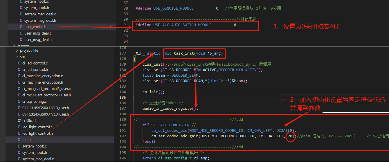
Fixed Gain Configuration for CI13LC Single-Microphone Solution
For the CI13LC single-microphone solution, disable dynamic ALC and add the following two lines of code after audio_in_codec_registe(); in the task_init function of main.c:
cm_set_codec_alc(HOST_MIC_RECORD_CODEC_ID, CM_CHA_LEFT, DISABLE);
cm_set_codec_adc_gain(HOST_MIC_RECORD_CODEC_ID, CM_CHA_LEFT, 15); // After disabling ALC, set fixed gain to 15dB for left channel; gain range: -18dB to 28dB, recommended range: 15-28dB; increase toward 28dB for lower noise environments, decrease toward 15dB for noisier environments. For 80-83dB noise levels, 15 is generally suitable.
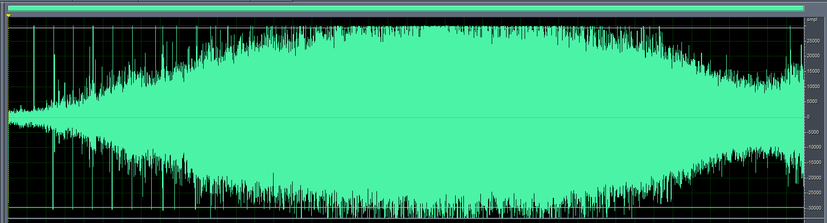
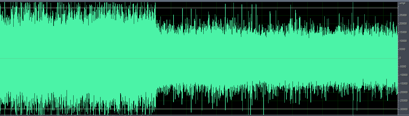
After applying this algorithm, we can observe that the audio signal amplitude is significantly reduced when using fixed gain.
2.4.2 Using Deep Noise Reduction Algorithm (CI130X Chip)
Some products generate significant noise during operation, such as range hoods, electric curtains, and smart clothes dryers, where the structural noise at the microphone can be substantial. For such products with poor recognition performance, the deep noise reduction algorithm can be used for optimization.
The deep noise reduction algorithm suppresses high noise generated by the device itself to improve recognition rates in low signal-to-noise ratio environments. Different application domains require corresponding domain-specific models. Currently, only noise reduction models for range hoods and curtains are provided.
-
In the
CI130X_SDK_ALG_PRO_X.X.XX\\projects\\offline_asr_alg_pro_sample\\project_file\\makefilefile, changeCI_ALG_TYPE := \$(USE_NULL)toCI_ALG_TYPE := \$(USE_DENOISE_NN) -
Copy the deep noise reduction algorithm model
[60003]nn_denoise_xx.binfromCI130X_SDK_ALG_PRO_X.X.XX\\external\\model\\nn_denoiseto theCI130X_SDK_ALG_PRO_X.X.XX\\projects\\offline_asr_alg_pro_sample\\firmware\\dnnfolder. Please refer to Noise Reduction Development Guide
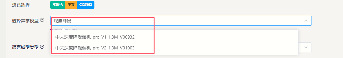
Note: Deep noise reduction requires using the CI130X chip with the corresponding front-end algorithm model. As shown in the figure below, when creating language model and acoustic models on the AI platform for deep noise reduction, please select the dedicated deep noise reduction model.
2.4.2 Poor Recognition of Specific Command Words
1. Add Positive Words in the Word Segmentation File
First, let’s explain the word segmentation file. The word segmentation file is the G.fst text file found in the compressed package downloaded after generating the model from our AI platform. For the format of the word segmentation file, please refer to the Model Generation via Word Segmentation File section.
Positive words are introduced to improve the recognition of target words within the word set, typically having the same output as the target word.
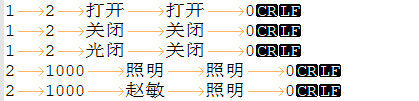
To add positive words, include words that sound similar to the command word. For example, in the figure below, “光闭” (guāng bì) is a positive word for “关闭” (guān bì, meaning “turn off”), which can enhance the recognition of “关闭”. Similarly, “赵敏” (Zhào Mǐn) is a positive word for “照明” (zhào míng, meaning “lighting”), which can enhance the recognition of “照明”.
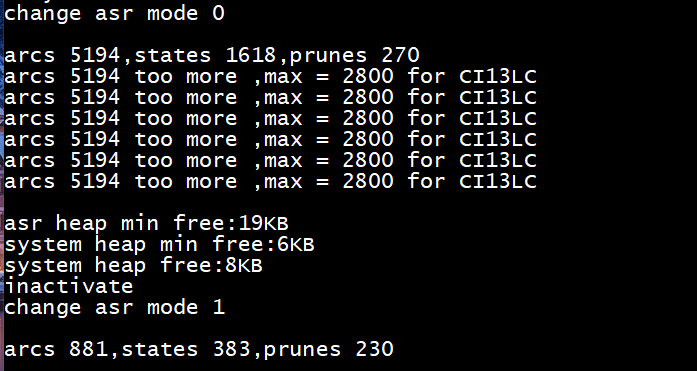
Note: Do not add an unlimited number of positive words. Adding positive words increases the number of nodes in the command word set. Ensure that no warnings such as “arcs xxxx too more” appear in the program’s log after running. If warnings like those shown in the figure below appear, you must reduce the number of entries to decrease the node count.
2. Check if Command Words Are Being Recognized as Negative Words
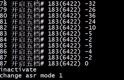
Negative words are introduced to reduce the recognition of target words within the word set. When a normal command word is recognized as a negative word, no recognition result will be output. To identify which negative word is being recognized, enable intermediate results in the SDK by setting the parameter of the ctr_asr_detail_result(int p) function to 1 and enable log printing. Observe the recognition results when speaking command words. If a negative word is recognized (indicated by a # symbol in the word segmentation file), remove it from the word segmentation file, regenerate the model, and test again.
3. Reduce Confidence Level
The confidence level adjusts the recognition sensitivity of command words to address misrecognition issues. This can be adjusted in the command word information table file located at \\projects\\offline_asr_alg_pro_sample\\firmware\\user_file\\cmd_info\\[60000] in the SDK project directory. If recognition is poor, try reducing the confidence level by 5 points at a time and observe the effect.
2.4.3 Poor Wake Word Recognition
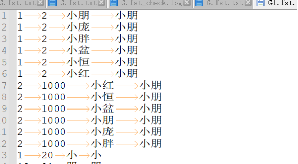
First, the design of wake words should follow our Voice UI Design Reference. Wake words cannot be chosen arbitrarily; they must meet certain specifications. If you encounter poor wake word recognition during development, you can refer to the optimization methods in section 2.4.2 of this document. For example, as shown in the figure below, if there is a wake word “小朋小朋” (Xiǎo Péng Xiǎo Péng) that is difficult to trigger due to user accents or other issues, you can add similar-sounding words as positive words to accommodate more accents.
2.4.4 False Wake-ups
False wake-ups occur when the voice wake-up system is triggered without an audio stream or when the audio stream does not contain the features or events required for wake-up. To address false wake-up issues, you can use our false wake-up and misrecognition testing tool for testing and optimization. Please refer to the False Recognition and False Wake-up Tool User Guide. False wake-ups are related to the confidence level. If the confidence level is set too high, the recognition rate may decrease. If it is set too low, while it may not affect the recognition rate, it may increase out-of-set misrecognition.misrecognition, which degrades the recognition experience. To balance recognition accuracy and false positives, here are several methods to confirm the confidence level, effectively improving the user experience with voice recognition.
A. Use Default Values from Chipintelli AI Platform Developers can directly use the confidence levels generated by the Chipintelli AI Platform. Typically, when an acoustic model is trained, we determine an initial confidence level through extensive testing. At this level, the recognition performance generally meets user requirements. Note that confidence levels may vary for the same entry across different acoustic models due to differences in training word frequencies. Therefore, confidence levels should not be directly transferred between different acoustic models.
B. Maximum Benefit Method for Confidence Adjustment If false wake-ups persist during testing, developers can use the maximum benefit method to adjust the confidence level. For example, with an initial wake word confidence of 25, conduct recognition rate tests using 10 voice samples (5 male, 5 female) in both quiet and noisy environments. Then, perform a false wake-up test with 12 hours of variety show audio (measured at approximately 65dB at the microphone). Based on the results, adjust the confidence level to 27 for optimal performance.
| Category | Confidence Distribution Data (in order) |
|---|---|
| False Wake-up Distribution | 23, 25, 25, 22, 22, 22, 24, 26, 24, 23, 30, 23, 24, 26, 22, 22 |
| Correct Recognition Distribution | 38, 39, 35, 37, 33, 39, 40, 36, 31, 29 |
C. Add Negative Words Adding negative words can effectively reduce false wake-ups. Our false wake-up and misrecognition testing tool can output audio files that trigger false wake-ups. Developers can manually identify these or use tools like WeChat Voice to transcribe them into text, then add them as negative words to the word segmentation file before regenerating the model.
2.4.5 In-Set Misrecognition
In-set misrecognition occurs when a word within the command word set is incorrectly recognized as another word in the same set. This can happen in the following scenarios:
- Longer Words Recognized as Shorter Words
This issue can be addressed by increasing the special word count for shorter words. The special word count is used when a shorter command word might be detected within a longer command word with similar content. You can adjust this in the command word information table file at \\projects\\offline_asr_alg_pro_sample\\firmware\\user_file\\cmd_info\\[60000].
For example, with “加热” (heat) and “加热三分钟” (heat for three minutes), saying “加热三分钟” might be recognized as just “加热”. The solution is to set a special word count for “加热”. After recognizing “加热”, the system will wait briefly to see if there’s a longer, more specific command. If found, it will discard the shorter match.
The count shouldn’t be set too high, as it will increase the response time. As a general rule, each character in the longer word requires 4 special word counts. For example, “加热三分钟” has 5 characters, so the special word count for “加热” should be set to 20, while “加热三分钟” should remain at 0.
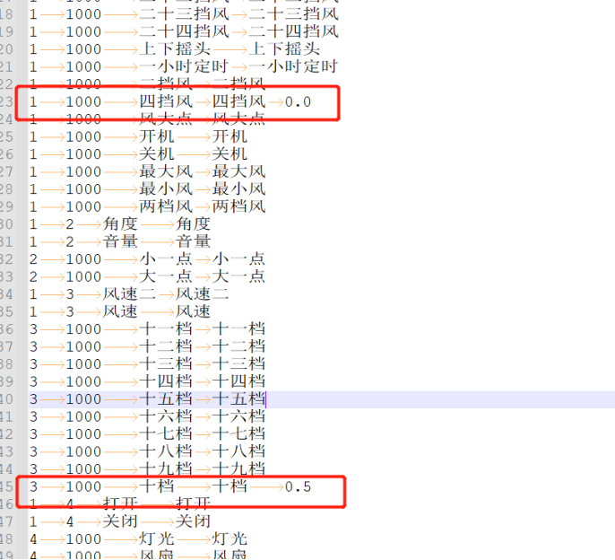
- Mutual Misrecognition Between Unrelated Command Words
For example, if “四档风” (fourth gear wind) is often misrecognized as “十档风” (tenth gear wind), you can add a Tab after “四档风” and related generalized words in the word segmentation file (as required by the format), followed by a weight of 0.0. For “十档” related word segments, add a weight of 0.5.
The weight ranges from 0.0 to 2.0, with higher numbers indicating lower weight and reduced recognition sensitivity. Start with 0.5 for “十档”, then test by selecting the word segmentation synthesis model on the platform, re-uploading to create the model, and observing the results. Adjust in small increments of 0.1.
2.4.6 Out-of-Set Misrecognition
Out-of-set misrecognition occurs when words outside the command word set trigger recognition after wake-up.
In actual use of voice products, this typically happens when unrelated audio sources (like TV sounds or casual conversation) trigger recognition during the wake-up period. The handling method is the same as for false wake-ups. You can use our false wake-up and misrecognition testing tool for testing and optimization.
Generally, voice products should have an appropriate wake-up exit time (e.g., 15 seconds), so the number of out-of-set misrecognitions is usually for reference only and not included in the acceptance testing standards.
2.4.7 Model Training
As a final optimization technique: if certain words have poor recognition due to insufficient or lack of frequency in the training set, you can provide recordings from 100+ speakers to enhance the training.