Single-Microphone Speech Recognition Project Development - CI13162
1. Preparation
1.1 Hardware Requirements
Module Board: Chipintelli CI13162 Module Board (Recommended Model: CI-F162GS02J)
Programming Tool: USB to TTL Serial Debug Tool (5V power supply supported)
Microphone & Speaker: Purchase microphones and speakers compatible with the module board. For bulk purchase specifications, refer to: Microphone Compatibility List
Testing Equipment: Personal Computer (Windows 7 or later recommended)
1.2 Software Requirements
Chipintelli Environment: Visual Studio Code
Development Framework: CI13LC_SDK_ASR_Offline_V2.0.15 (Always use the latest version if available)
1.3 Documentation
Official Resources
2. Software Configuration
2.1 Development Environment Setup
-
Download and install Visual Studio Code
-
Download the relevant SDK and open it with VSCode
-
Install the compilation plugin and GCC toolchain to make the code.bin file for firmware generation
For detailed procedures, refer to: Compilation Software Installation and Usage
2.2 Development Tools Configuration
Programming Tool
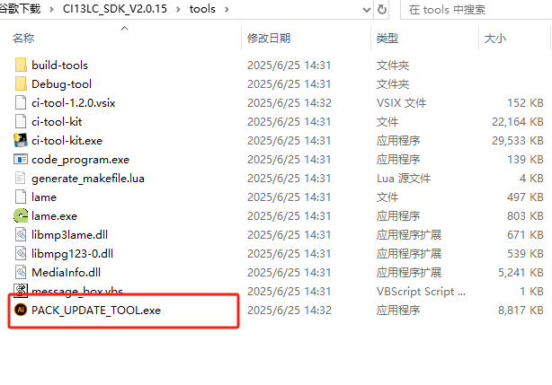
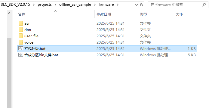
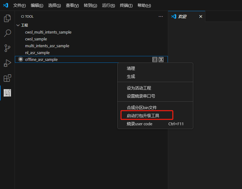
PACK_UPDATE_TOOL.exe is located in the tools folder under the SDK root directory. You can also use “pack_upgrade.bat” in the Firmware folder or right-click on the SDK compilation interface and select “Start Packaging Tool” to open it. The usage can be learned from the documentation in section 2.1 or viewed in the “Chipintelli - Firmware Update & Print Operation Documentation” in the module design materials downloaded in section 3.2.
Testing Tool
Any serial port debugging software available on the market can be used, typically with a communication baud rate of 9600, to test the voice module’s recognition and playback functions through computer communication. For download and quick start, please refer to: UART Serial Port Debugging Tool User Guide.
3. Hardware Development
3.1 CI-F162GS02J Module Features
Chip Parameters
The CI-F162GS02J module is equipped with the CI13162 chip, which integrates Chipintelli’s self-developed Brain Neural Network Processor (BNPU V3.5) and CPU core. The system can reach a main frequency of 210MHz, with built-in 288KB SRAM and 2MB Flash. It includes a PMU power management unit, RC oscillator, single-channel high-performance low-power Audio Codec, and multiple peripheral control interfaces such as UART, I2C, IIS, PWM, GPIO, and PDM. The chip requires only a small number of peripheral components like resistors and capacitors to implement various intelligent voice product hardware solutions, offering excellent cost performance.
Interface Resources
The module is compact in size (30mm × 40mm) with an operating voltage range of 3.6V to 5.5V. It features an onboard power amplifier, one microphone input, one speaker output, and interfaces for 5V power supply and UART. The module can be used by simply connecting a microphone and speaker for direct power supply. Alternatively, it can be connected to the main control board of a product via UART using connectors, powered by the product’s 5V power supply, with UART communication or GPIO control without requiring soldering. The module includes two 3.5mm screw holes for easy fixing and installation.
For more detailed information, please refer to the documentation in section 1.3.
3.2 Peripheral Circuit Design
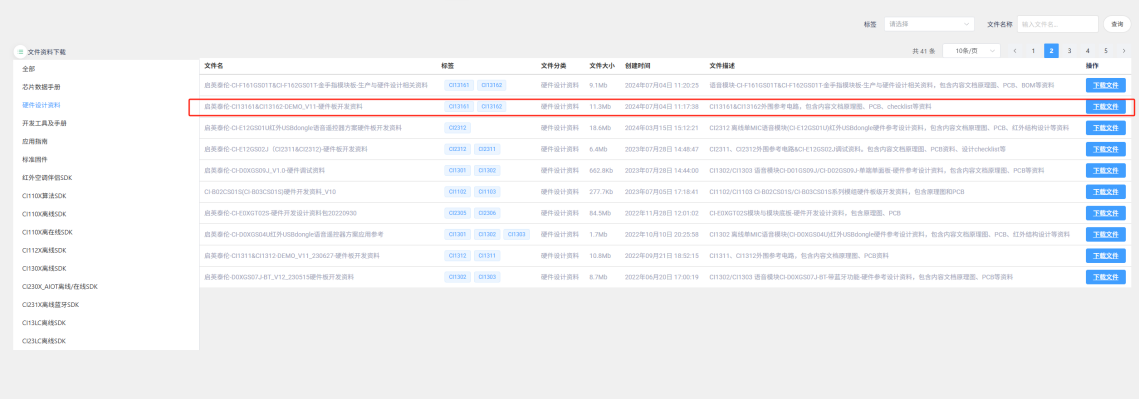
Detailed documentation can be downloaded by clicking Hardware Design Materials. This section does not provide a detailed introduction. The materials include PDF version schematics, and professional software like Altium Designer is required to view the PCB files. The “Hardware Debugging Documentation” in the materials contains hardware debugging and troubleshooting information that can be very helpful.
4. Software Development
4.1 Firmware Development Methods
Generally, the program modifications only include: UART communication protocol, command word ID or semantic ID judgment processing, chip version, and other basic macro definitions. These contents have been integrated into the “Offline Speech Recognition Large Model Application” of the Chipintelli AI Speech Development Platform, allowing settings through forms, values, and switches to automatically generate corresponding firmware and modifiable SDK. The following illustrates two methods: how to use the platform to create basic firmware and how to synthesize firmware using the SDK and command word tables.
For an overview of the program structure, refer to: SDK Software Structure.
There are also video tutorials available for the firmware creation process: Video Tutorials.
Creating Basic Firmware Using the Platform
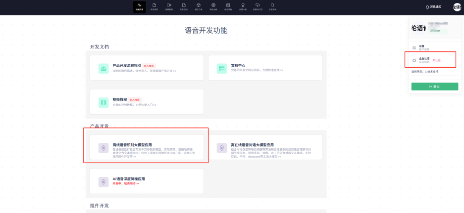
First, click to enter the “Offline Speech Recognition Large Model Application”. Note that it’s recommended to complete company certification in the top-right corner when using the platform to create firmware, as this unlocks more advanced optimization features.
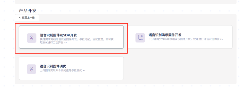
Click on “Speech Recognition Firmware and SDK Development”
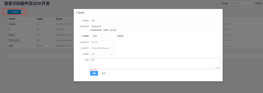
Create a new project. Fill in the “Product Name” and “Description” as needed. Select “Single-Microphone Speech Recognition” for the “Application Solution”. The “Product Type” should match your actual needs, mainly affecting the subsequent domain recognition model selection. After selecting chip model “13162”, other options will be automatically determined. If there are newer versions available in the future, you can select them.
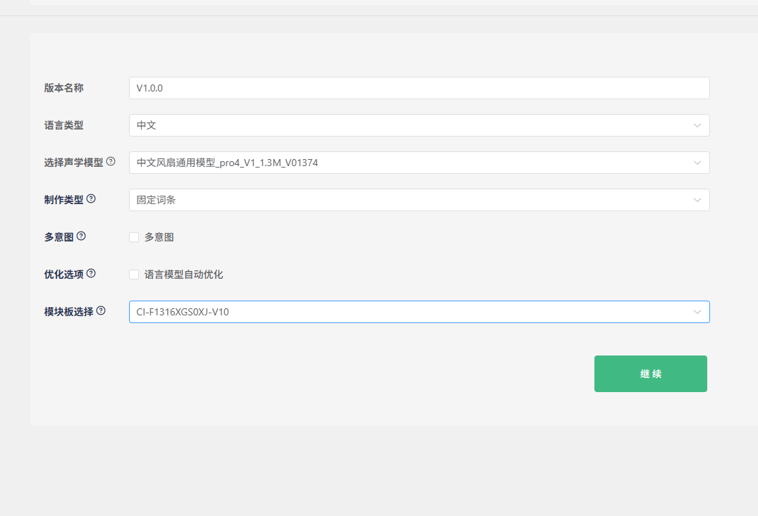
Keep the default “Version Name”. For “Language Type”, we’ll use Chinese as an example. “Select Acoustic Model” is crucial as it affects the noise reduction performance and the sensitivity to command words in real-world environments. Generally, newer and larger models perform better. In the example above, “pro4” is the model version (currently the latest), “1.3M” is the model size (the maximum size that the 13162 chip can accommodate), and “1374” is the model ID for differentiation. For “Creation Type”, you can choose between fixed phrases and natural speech - we’ll demonstrate with fixed phrases here. The “Optimization Options” are selected by default. If you plan to create natural speech or commands in other languages later, you can uncheck this to speed up SDK generation.
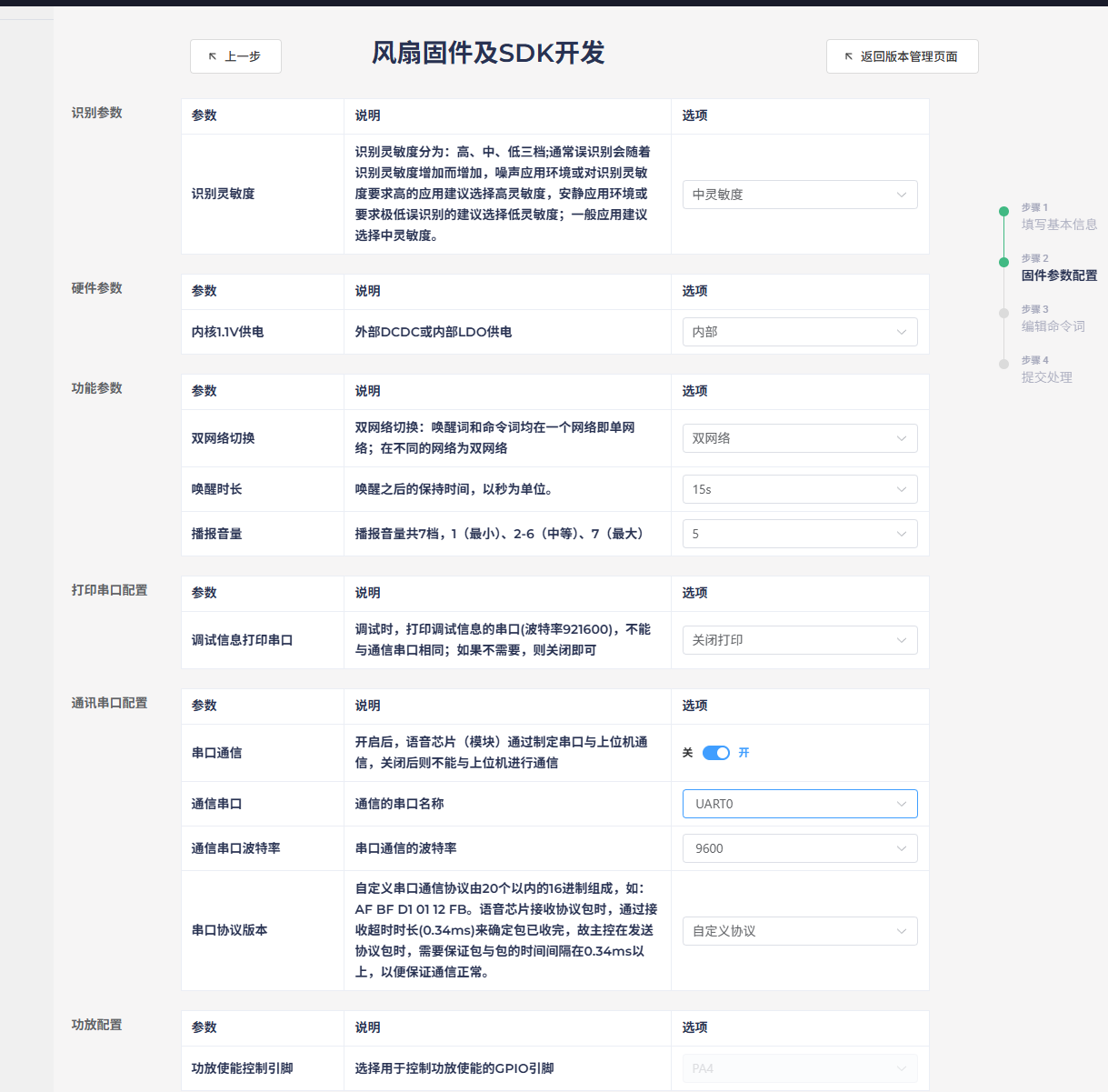
Sensitivity can be set to medium or high (adjustable later). Keep power supply options as default. For network switching, dual-network is generally recommended as it better reduces false triggers with wake words. Adjust the wake-up duration and initial volume as needed. Since the module only has one UART0 for external communication, change the debug UART to another option. Select UART0 for the communication port and modify the baud rate as needed. The UART protocol must be custom-defined and filled in later. Keep the amplifier configuration unchanged and click “Continue”.
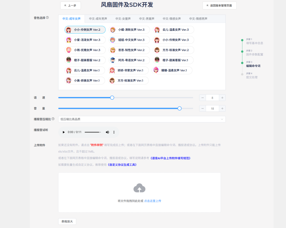
Modify the voice characteristics, speech rate, and volume of the broadcast sound as desired. For compression ratio, prioritize lower compression for higher sound quality. Click “Download Example” to get the command word table.
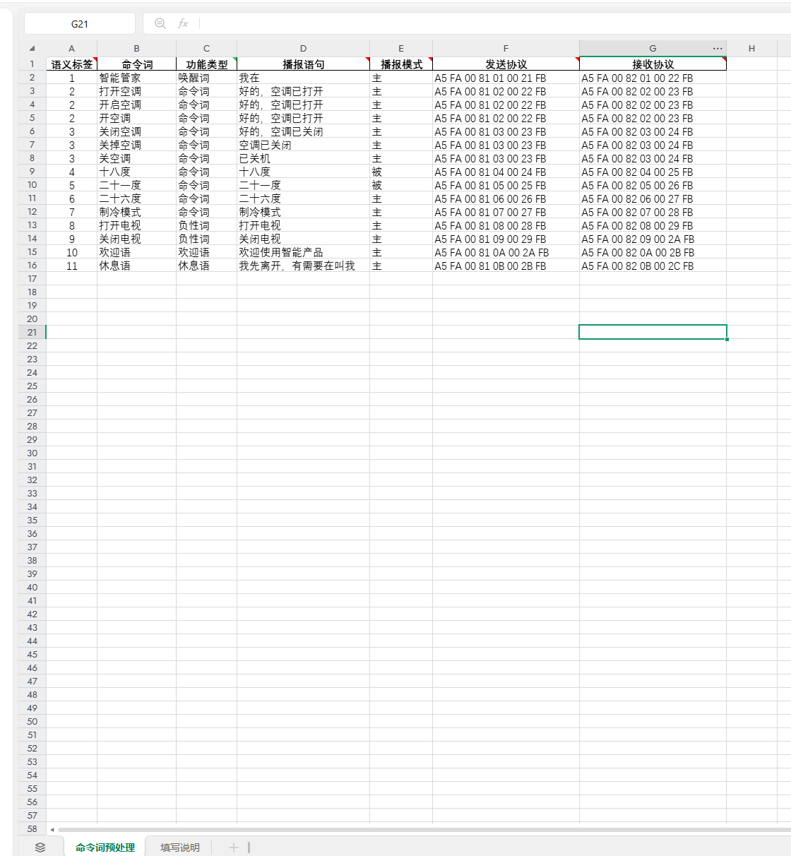
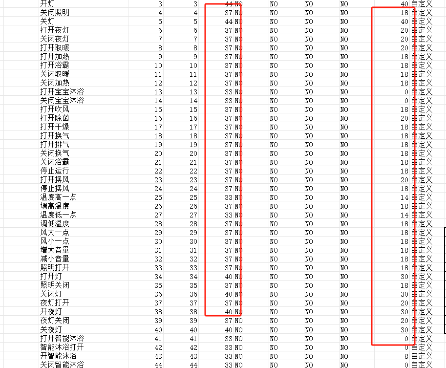
Using the downloaded example: The first column contains semantic labels to distinguish each entry and avoid conflicts.
The second and third columns contain the unique wake word (e.g., “Smart Butler”), which prevents false triggers during idle time. After speaking the wake word, other command words will only be effective within the 15-second wake-up window. Triggering a command will extend this window by another 15 seconds; otherwise, the wake word will be required again. Command words are instructions for external control, varying by product. “Turn on TV” and “Turn off TV” serve as negative examples to reduce false triggers of similar commands like “Turn on AC” after wake-up. These can be added or removed as needed. The welcome message plays on power-up to guide users, while the rest message plays after 15 seconds of inactivity. All these entries will send corresponding protocols via UART0 when triggered. If no protocol is specified, no data will be sent. Additionally, the third column includes functions like “Increase Volume,” “Decrease Volume,” “Maximum Volume,” “Minimum Volume,” “Enable Broadcast,” and “Disable Broadcast,” which control the corresponding voice module functions as their names suggest.
The fourth column contains the feedback messages corresponding to the third column. Whether these messages are played depends on the active/passive type in the fifth column and whether the corresponding receive protocol is sent by the computer or electronic control in the seventh column.
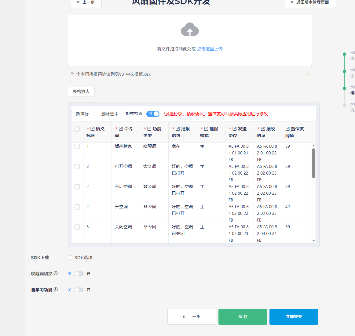
After filling out the table, click “Upload” in the creation interface to load the table. Note that Chinese command words should not contain English words, spaces, or punctuation marks, as this will cause format validation to fail, preventing firmware generation.
It’s recommended to check the “Download SDK” option, as this allows you to modify the program logic directly in the downloaded SDK if needed. Features like wake word switching can be configured based on actual requirements and won’t be detailed here. After clicking “Submit,” wait for the process to complete, and the firmware and SDK will be available for download and testing.
Creating Basic Firmware Using SDK
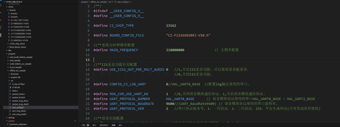
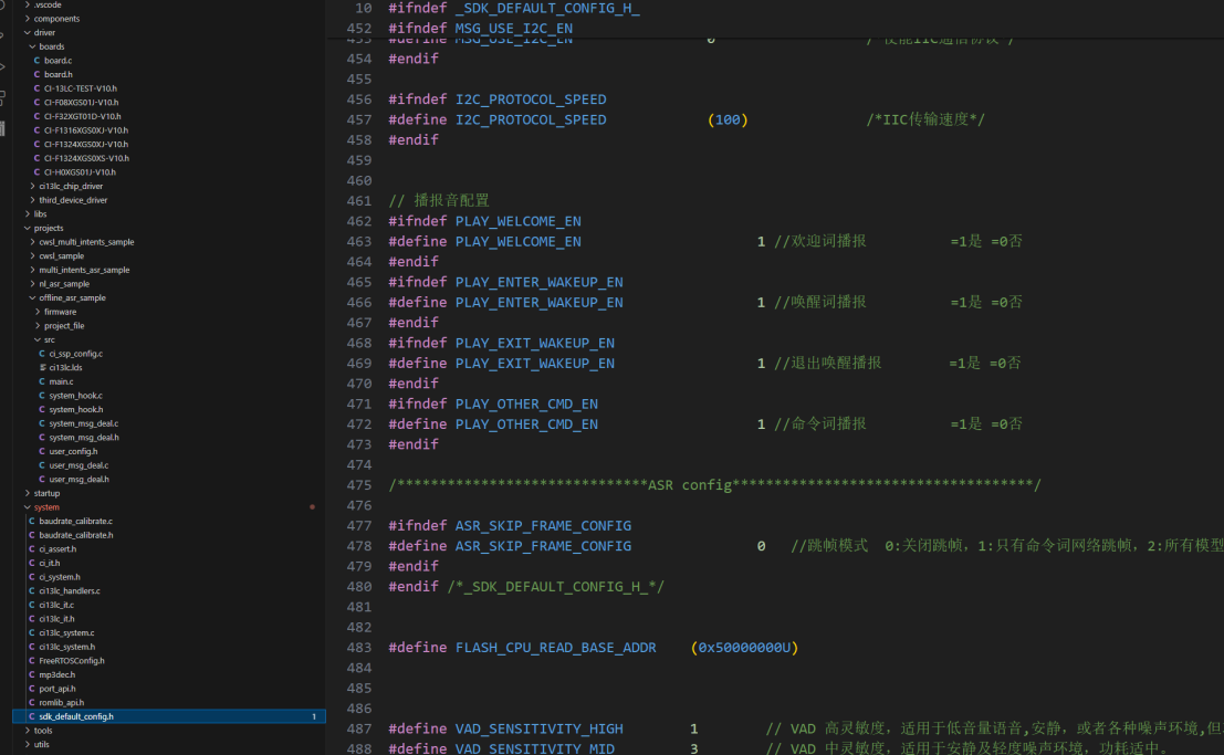
After installing the development environment according to the steps in section 2.1, open the SDK and configure macro definitions in user_config.h and sdk_default_config.h for chip model, board configuration, UART settings, active/passive broadcasting, etc.
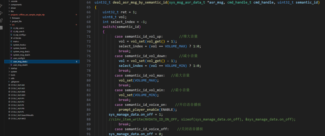
Configure volume control and other functions in the deal_asr_msg_by_cmd_id or deal_asr_msg_by_semantic_id functions.
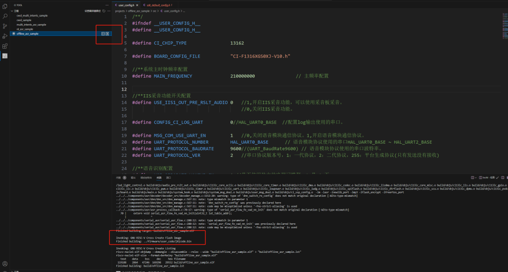
After modifying the code, switch to project compilation in the left toolbar, click “Clean” and then “Build” to generate the modified code.bin. If there are any errors, use Ctrl+F to locate and fix them. A successful compilation will display: Finished building: ../firmware/user_code/[0]code.bin.
For more program control, refer to Chip Drivers and make calls in functions like userapp_initial (user initialization). This SDK uses the Free RTOS operating system. For advanced programming such as software timers, please refer to the relevant learning materials.
For the remaining command words, broadcast sounds, command word information table creation, and subsequent firmware synthesis and downloading, please refer to: Command Words and Firmware Production Guide.
4.2 Self-Learning and Natural Speech Solutions
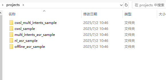
The 13162 SDK includes multiple project templates for developing various solutions, including self-learning, natural speech, and fixed phrase solutions. Below is an introduction to each solution’s application and development.
Self-Learning Solution
The self-learning solution allows binding new voice commands by learning wake words and command words based on preset instructions, making it compatible with users who have strong accents or unclear pronunciation, such as various regional dialects.
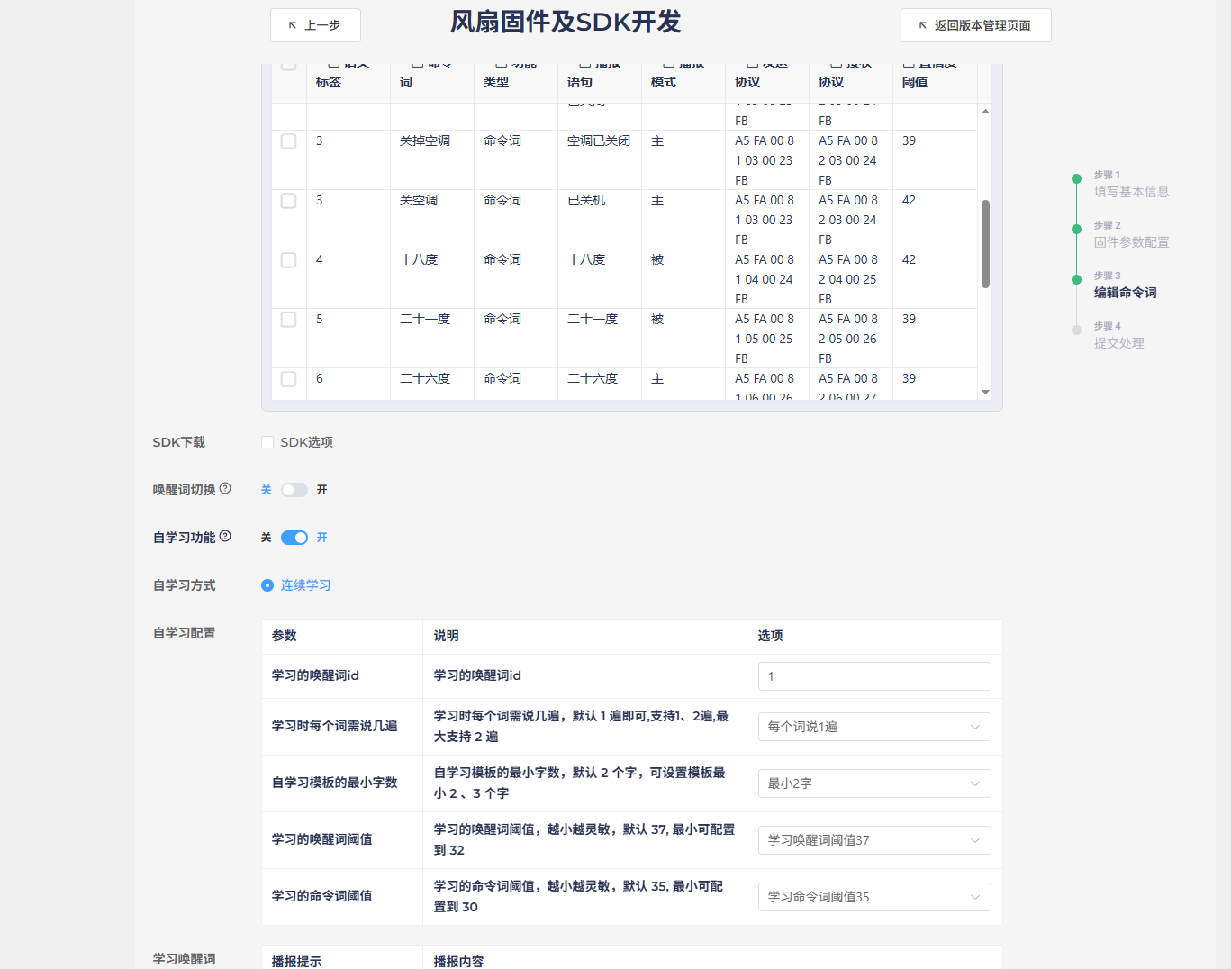
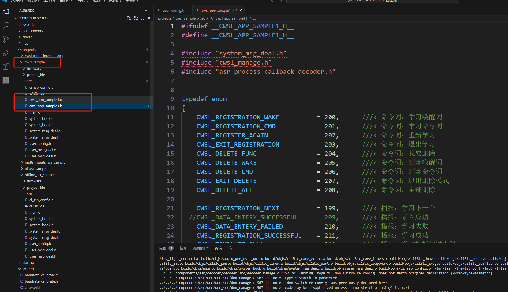
For self-learning development, it’s recommended to enable the self-learning feature at the end of section 4.1’s platform-based firmware creation. Simply fill in the content as prompted to generate the corresponding functionality. The main control and modification parts in the SDK program are located in projects\cwsl_sample\src\cwsl_app_sample1.c and cwsl_app_sample1.h. For detailed development documentation, see: Offline Commands Self-Learning Quick Start
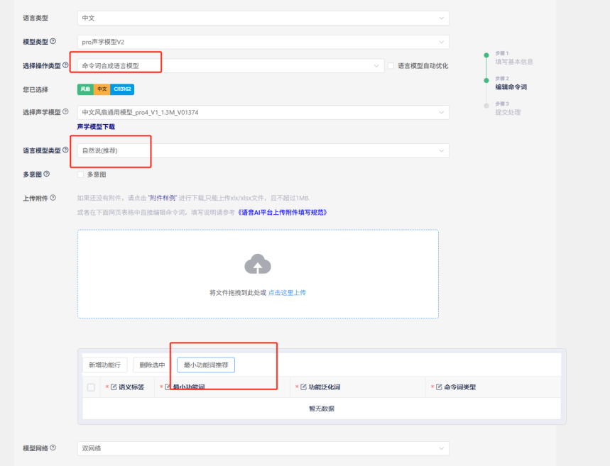
Natural Speech Solution
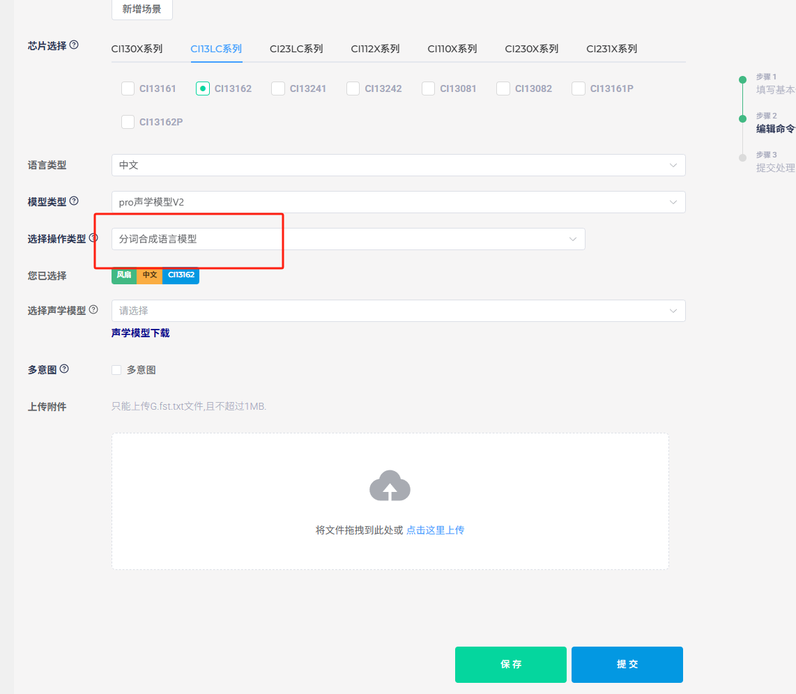
The natural speech solution offers broader and more natural recognition than fixed phrases, providing a more natural voice interaction experience. When selecting the natural speech project in the SDK, the program development content is similar to fixed phrases but includes additional algorithms. For command word creation, it’s recommended to use the “Language Model Development” entry mentioned at the end of section 4.1. Select “Command Word Synthesis Model” as the operation type (without checking the auto-optimization option) and choose “Natural Numbers (Recommended)” as the model type. You can then select pre-optimized functional phrases from Chipintelli’s recommendations, with each function having multiple natural expressions. For additional functions, you’ll need to upload a command word template table.
5. Recognition Optimization
5.1 Acoustic Model Selection and Principles
Noise Reduction Training
As mentioned in section 4.1 when selecting an acoustic model, it’s important to choose a model that matches the product description. This is because our domain-specific models are trained with actual product noise during the training process. Different products like fans, bathroom heaters, and range hoods produce different types of noise at various power levels, so training with just the highest noise level may not yield the best results.
Command Training
Since commands vary across products, it’s impractical to include training sets for all possible commands within the chip’s memory constraints. Therefore, we categorize models into different domains and enhance training with high-frequency phrases, which proves to be a more effective approach.
For niche products without a corresponding domain model, selecting an acoustic model based on which domain’s noise and phrases most closely match the actual product is recommended.
5.2 Language Model Optimization
Confidence and Special Word Count Optimization
The command word information table [60000]cmd_info.xlsx contains confidence levels and special word counts. The fourth column in the table represents the confidence level, which is the threshold for how closely the user’s voice matches the trained command model. Values above this threshold are considered successful recognitions. Adjusting this value up or down can reduce sensitivity to minimize false triggers or increase sensitivity at the cost of potentially more false positives. The ideal confidence level should be determined through practical testing.
The ninth column in the table is the special word count. Increasing this value requires the algorithm to exceed the confidence threshold more times for the preceding command words, which helps reduce misrecognition of longer commands as shorter ones. For example, to prevent “turn on the bathroom light” from being misrecognized as “turn on the light,” you would increase the special word count for “turn on the light.”
Note: After modifying the command word information table, you must click “make_partition _bin.bat” again; otherwise, the newly packaged firmware will retain the previous content.
Optimization for Single Word Recognition
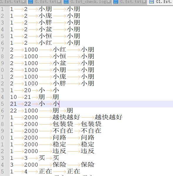
As shown in the figure, if a wake word like “Xiaopeng Xiaopeng” is difficult to recognize due to user accents or other issues, you can add similar-sounding alternatives to the word segmentation to improve accent compatibility.
The first two columns in the word segmentation file contain numbers like 1, 2, 3, 1000, and 2000, which represent recognition intermediate points or branch points. For example, when recognizing “Xiaopeng Xiaopeng,” the system first detects “Xiaopeng” and then detects it again, using the two matches to output the correct result.
- The number 1 is the unified starting point for each complete command word or garbage word.
- Numbers 2, 3, 4, and 5 are different recognition nodes used for longer command words or command words with common parts.
- 1000 is the endpoint for command words, and 2000 is the endpoint for garbage words. Only words ending with 1000 will be output as recognized results. Words ending with 2000 are used to reduce false wake-ups or misrecognitions and can include common daily words. Some are automatically added during optimization, but you can manually add more if customers report frequent false triggers or misrecognitions.
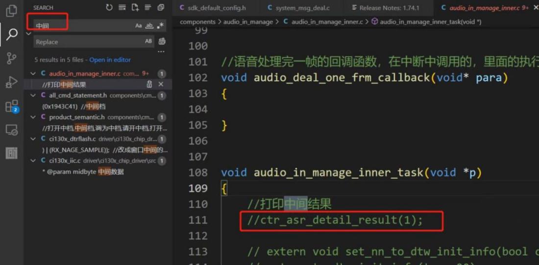
Word segmentation optimization can be combined with the intermediate result logging function.
To enable the intermediate result logging function, search for “intermediate” in the top-left corner, find the relevant comments, and uncheck the default commented sections to enable output. The log will display recognition scores and related result words during recognition, helping you adjust word segmentation based on the output.
Word Segmentation Upload Location
6. Effect Evaluation and Problem Analysis
6.1 Effect Evaluation
Full-Machine Testing
The most intuitive method is to install the system in the actual device and conduct real-user testing to determine if adjustments are needed.
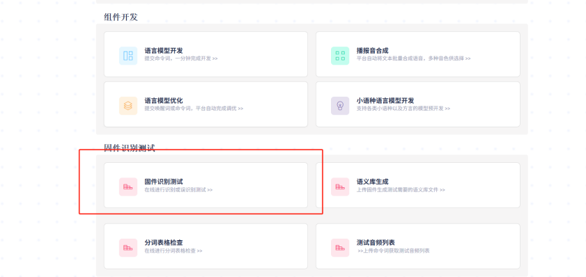
Platform Firmware Recognition Testing
The Chipintelli AI Platform can provide test results by uploading firmware and test audio, offering more scientific conclusions through data analysis. The figure below shows the test entry point.
Soundproof Laboratory Full-Machine Testing
This method combines the above two approaches, using the complete device and audio test sets in a professional testing environment to derive scientific conclusions that closely match real-world conditions.
6.2 Common Issues and Solutions
| Issue Description | Possible Causes | Solutions |
|---|---|---|
| Wake-up Failure | 1. Excessive environmental noise | 1. Optimize the acoustic model |
| 2. Poor microphone placement | 2. Adjust microphone position | |
| 3. Wake word confidence too high | 3. Lower wake word confidence | |
| Frequent False Wake-ups | 1. Wake word confidence too low | 1. Increase wake word confidence |
| 2. Environmental noise interference | 2. Add environmental adaptation training | |
| 3. Insufficient model generalization | 3. Optimize wake word design | |
| Low Command Word Recognition Rate | 1. Similar-sounding command words | 1. Optimize command word design |
| 2. Insufficient model training | 2. Optimize the acoustic model | |
| 3. Background noise interference | 3. Adjust microphone position | |
| Slow System Response | 1. High algorithm complexity | 1. Optimize algorithm parameters |
| 2. Insufficient system resources | 2. Remove unnecessary functional modules | |
| 3. Inefficient task scheduling | 3. Adjust task priorities |
6.3 Important Notes
Structural Considerations
Pay special attention to the microphone’s structural placement. Refer to the Product Structural Design guide for determining the optimal microphone installation position.
Testing Considerations
Many factors can affect recognition performance. If structural and installation issues are confirmed or cannot be changed, refer to the “Hardware Debugging Documentation” folder in the module design circuit package downloaded in section 3.2 to troubleshoot hardware, software, and microphone noise issues.