CI13241 & CI13242 Development Kit
Overview
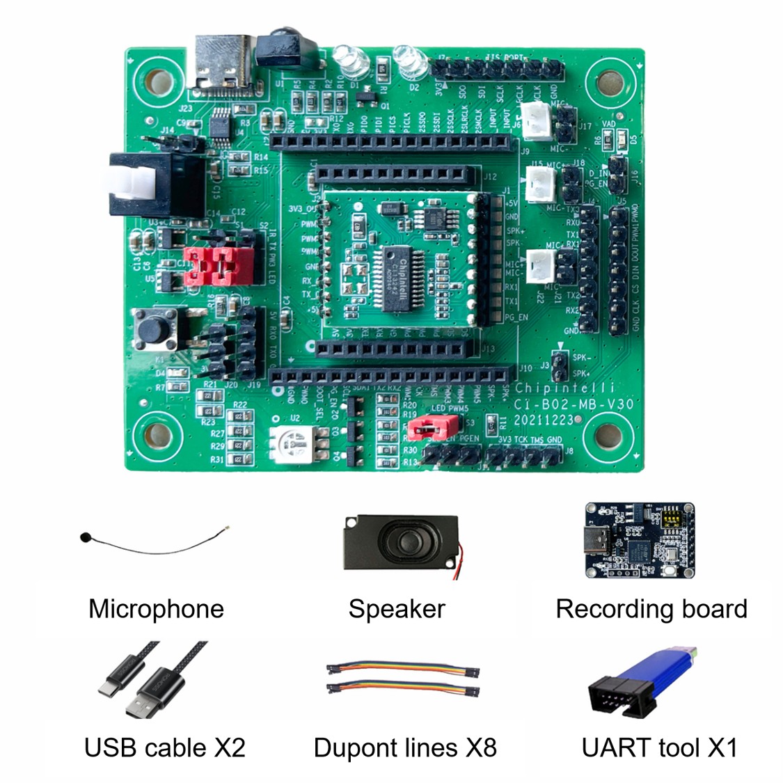
The CI13241 & CI13242 development board consists of a module board (CI-F241GS01S/CI-F242GS01S, CI-F24XGS01S), a universal baseboard (CI-B02-MB), a microphone, and a speaker. The CI13241 & CI13242 development kit includes the CI1324X development board, a serial debug tool, an audio capture board, a USB cable, and DuPont wires. The CI13241 & CI13242 development board comes with standard firmware pre-installed, allowing wake-up and recognition using the wake word “Smart Butler.” New firmware can also be downloaded using the serial debug tool included in the development kit. This document provides a progressive introduction from basic to advanced topics, covering the composition and concepts of the development board and kit, differences between CI13241 and CI13242 development kits, introduction to the universal baseboard, features of the development kit, and application examples. First, let’s briefly explain the composition and concepts of the development board and kit.
The composition of the CI13241 & CI13242 development board is shown below:

The composition of the CI13241 & CI13242 development kit is shown below:
Development Board Model Differences
The main difference between the CI13241 and CI13242 development boards lies in their main chips. There are two chip models: CI13241 and CI13242. The specific differences are shown in the table below:
| No. | Development Board Model | Main Chip Model | FLASH Size | Difference Description |
|---|---|---|---|---|
| 1 | CI13242 Development Board | CI13242 | 2MB | Supports medium model, more command words |
| 2 | CI13241 Development Board | CI13241 | 1MB | Supports smaller model, moderate number of command words |
Universal Baseboard Introduction
The ChipIntelli universal baseboard CI-B02-MB (hereinafter referred to as the baseboard) can be paired with CI110X series SMD modules, CI112X series SMD modules, CI13LC series SMD modules, and CI13LCX series SMD modules to form different series of evaluation kits. It enables basic voice recognition and playback function demonstrations, interface expansion applications, and user firmware development verification. The following is a detailed introduction to the universal baseboard.
Appearance of the baseboard:
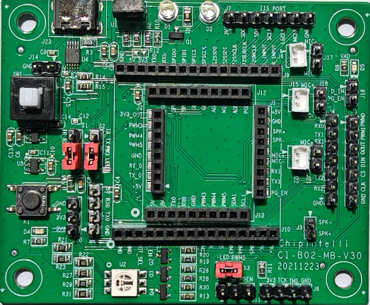
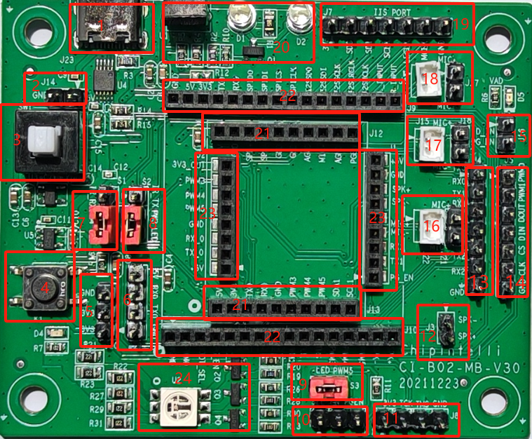
The baseboard features rich interfaces. The specific interface functions, signal names, and descriptions are shown in the table below:
Functional definitions of each interface on the baseboard:
| Ref. | Position | Function & Definition | Description | Notes |
|---|---|---|---|---|
| J23 | 1 | TYPE-C Port | TYPE-C Interface 5V Power Input Firmware Programming Port |
Note: This port is both for power supply and data programming |
| J14 | 2 | 5V GND |
5V (5V Power Interface) GND (Ground Pin) |
2PIN-2.54 Header 5V Power Input |
| SW1 | 3 | Baseboard Power Button | Press to power off Release to power on |
Check if power indicator is lit |
| K1 | 4 | Extension Button | Trigger Function | Not used currently |
| J20 | 5 | 3.3V, 3.3V, GND | 3PIN-2.54 3.3V Power Output |
Max output 50mA |
| J19 | 6 | 5V RX0 TX0 GND |
5V (5V Power Input) RX0 (UART0 Receive) TX0 (UART0 Transmit) GND (Ground Pin) |
4PIN-2.54 Alternative Firmware Programming Port |
| S1 | 7 | IR_RX PWM4 LED |
Short PWM4 to IR_RX for IR Receive Function Short PWM4 to LED for Green LED Control |
3PIN-2.54 PWM4 Function Selection |
| S2 | 8 | IR_RX PWM3 LED |
Short PWM3 to IR_TX for IR Transmit Function Short PWM3 to LED for Blue LED Control |
3PIN-2.54 PWM3 Function Selection |
| S3 | 9 | PWM5 LED |
Short PWM5 to LED for Red LED Control |
2PIN-2.54 PWM5 Function Selection |
| J11 | 10 | SEL EN PGEN |
Short EN to SEL for JTAG Debug Mode Short EN to PGEN for Firmware Update Mode |
Usually use update mode for firmware download Connect jumper cap between EN and PGEN |
| J8 | 11 | 3.3V TCK TMS GND |
3.3V (Max 50mA) TCK (JTAG_TCK) TMS (JTAG_TCKTMS) GND (Ground Pin) |
4PIN-2.54 JTAG Debug Pins, not available for CI13LC/CI13LCX series |
| J3 | 12 | SPK- SPK+ |
Connect to 8Ω/2W or 4Ω/3W Speaker | 2PIN-2.54 Speaker interface, no polarity |
| J4 | 13 | TX0 RX0 TX1 RX1 TX2 RX2 GND |
TX0 (UART0 Transmit) RX0 (UART0 Receive) TX1 (UART1 Transmit) RX1 (UART1 Receive) TX2 (UART2 Transmit) RX2 (UART2 Receive) GND (Ground) |
Connect to UART0, UART1 UART2 not available for voice module UART0 is connected to J19’s UART0 |
| J5 | 14 | PWM0 PWM1 DOUT DIN CS CLK GND |
PWM0 (PWM0 Interface) PWM1 (PWM1 Interface) DOUT (Extended SPI) DIN (Extended SPI) CS (Extended SPI) CLK (Extended SPI) GND (Ground) |
7PIN-2.54 Extended Function Port |
| J16 | 15 | D-IN PG_EN |
D-IN (Extended SPI Input) PG_EN (Program Enable) |
PG_EN has same function as J11’s PGEN pin |
| J21 J22 |
16 | MIC+ MIC- |
MIC+ (Microphone Positive) MIC- (Microphone Negative) |
Supports 2.54mm or 1.25mm pitch microphones, compatible with C22 GS01S/D02 GS01S/D03 GS01S/F24GS01S |
| J15 J18 |
17 | MIC+ MIC- |
MIC+ (Microphone Positive) MIC- (Microphone Negative) |
Supports 2.54mm or 1.25mm pitch microphones, compatible with B02GS04S/B03GS04S modules |
| J6 J17 |
18 | MIC+ MIC- |
MIC+ (Microphone Positive) MIC- (Microphone Negative) |
Supports 2.54mm or 1.25mm pitch microphones, no compatible module currently |
| J7 | 19 | 3.3V SDO SDI SCLK LRCK MCLK GND |
3.3V (Power Output) SDO (IIS_SDO) SDI (IIS_SDI) SCLK (IIS_SCLK) LRCK (IIS_LRCK) MCLK (IIS_MCLK) GND (Ground) |
Supports connection to audio capture board for audio collection |
| J1 D1 D2 |
20 | IR_RX IR_TX |
IR Transmit IR Receive |
Requires shorting interfaces 7 and 8 for configuration |
| J12 J13 |
21 | Module Interface | Connect to Voice Module | CI-B02GS04S CI-B03GS04S |
| J9 J10 |
22 | Module Interface | Connect to Voice Module | No compatible module currently |
| J1 J2 |
23 | Module Interface | Connect to Voice Module | CI-C22 GS01S CI-D02 GS01S CI-D03 GS01S CI-D01 GS01S CI-F24GS01S |
| U2 | 24 | RGB LED | Controlled by PWM3/PWM4/PWM5 | Requires shorting interfaces 7, 8, 9 for configuration |
For more detailed information about the baseboard interfaces and their applications, please refer to the baseboard schematic file below:
Development Kit Features
The development kit consists of a development board, serial debug tool, audio capture board, USB cable, and DuPont wires. The microphone enables voice input, the speaker enables audio playback, the serial debug tool facilitates firmware downloads and debug information printing, and the audio capture board enables voice data collection and analysis. The following describes how to connect each component to the development board.
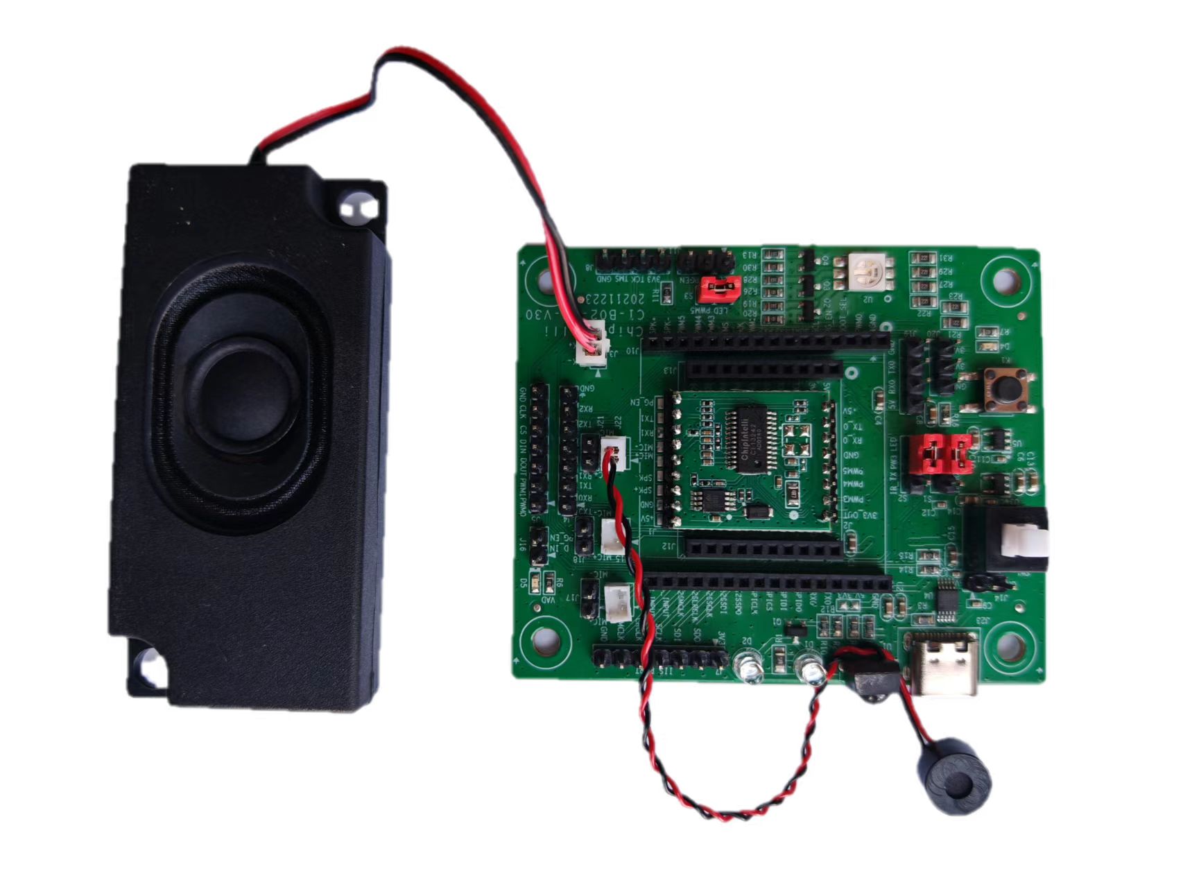
For the CI13241 & CI13242 development board, the microphone connector is J22. Note that the microphone has polarity (positive/negative) and the connector is keyed to prevent incorrect insertion. The speaker connector is J3, which is non-polarized. The connection diagram for the development board’s microphone and speaker is shown below:
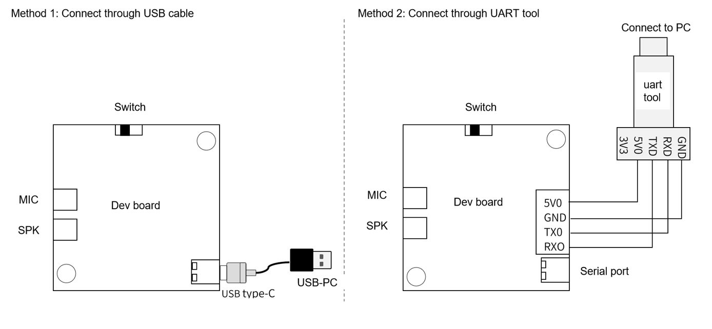
There are two methods for downloading firmware to the development board. The hardware connection diagrams for both methods are shown below:
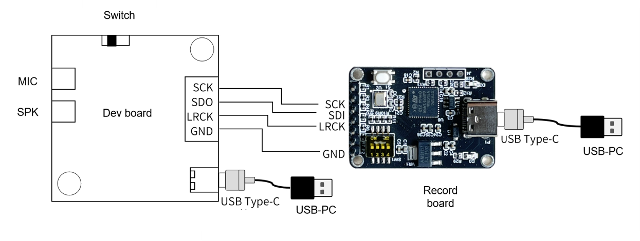
The hardware connection diagram for development board communication and log printing is shown below:
Application Example
The following example demonstrates how to use this development kit by programming the module board with standard firmware, waking it up with voice commands, and controlling it through voice to get audio feedback from the development kit.
Note: When purchasing our CI-F242GS01S/CI-F241GS01S module samples, they come with basic firmware that provides the following functionality: when a command word is recognized, the corresponding response will be played through the speaker.
Preparation
To complete this example, you’ll need the materials listed in Table 2. For CI13241 chip development, you can choose the CI-F241GS01S module. The firmware size should be less than 1MB.
| Name | Description | Quantity | Purchase Method |
|---|---|---|---|
| CI-F242GS01S CI-F241GS01S |
Voice Module Board | 1 | Purchase Samples |
| CI-B02-MB | Module Baseboard | 1 | Purchase Samples |
| Microphone | Audio Capture | 1 | Purchase Samples |
| Speaker | Audio Playback | 1 | Purchase Samples |
| USB Type-C Cable | Connect to Computer for Firmware Programming and Power |
1 | Mobile phone data cable or self-purchased |
Connection Diagram
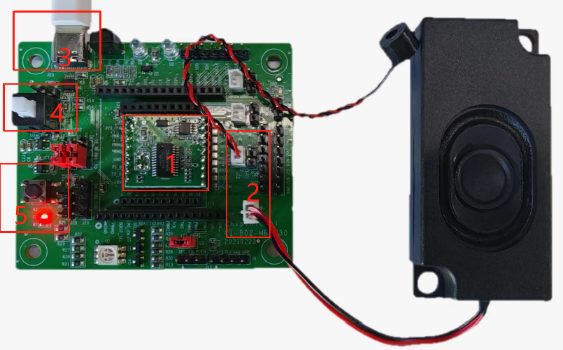
The connection diagram for this example is shown below:
Connection method:
- Insert the CI-F24XGS01S module board into the position marked by red box 1 in the figure above, paying attention to the correct orientation (already connected when shipped);
- Connect the microphone to the socket marked by red box 2 in the figure above (note: align MIC+ with MIC+ and MIC- with MIC- according to the silkscreen), with the black wire oriented toward the speaker socket;
- Connect the speaker to the socket marked by red box 3 in the figure above (no polarity needed).
Operation Steps
After connecting the development kit according to the connection diagram above, follow these steps to operate:
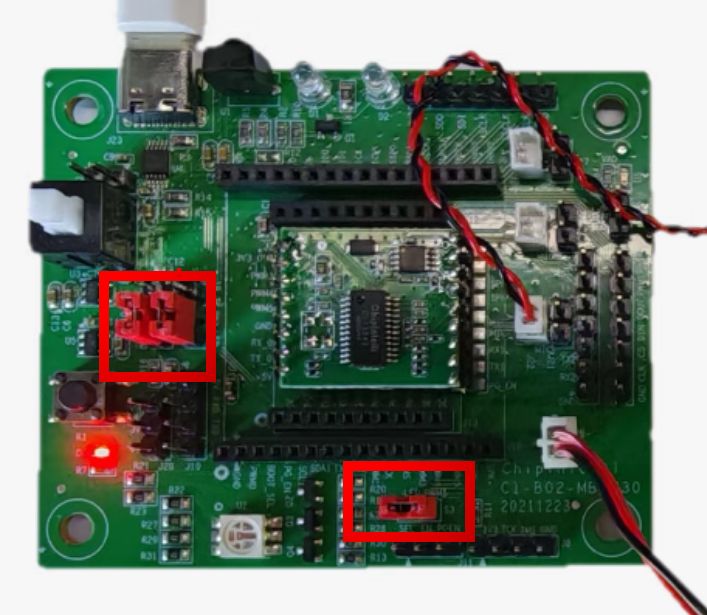
- Connect one end of the Type-C cable to a computer or 5V charger USB port, and the other end to the power interface of the baseboard (marked by red box 3 in the connection diagram);
- Press the power switch (marked by red box 4 in the connection diagram). When the red LED on the baseboard lights up (marked by red box 5 in the connection diagram), it indicates that the power is on;
- After powering on, you will hear “Welcome to Smart Butler, you can wake me up by saying ‘Smart Butler’“. At this point, say “Smart Butler” and you should hear the development board respond with “Hello,” indicating that the module, power supply, microphone, and speaker are all properly connected;
- If any abnormalities occur, please refer to the “Frequently Asked Questions” section at the end of this document. If problems persist, please contact our technical support team for assistance.
Standard Module Command Words and Corresponding Voice Responses
Our standard modules come pre-programmed with standard firmware. To use, first say the wake word “Smart Butler”. After hearing the response “Hello,” you can then say other command words. When you hear “Thank you for using,” it means the device has exited the wake state and you’ll need to say “Smart Butler” to wake it again.
The following table lists the command words and their corresponding voice responses in our standard firmware:
Note: Some command words may be added or removed based on specific requirements without prior notice.
| Command Word | Response | Command Word | Response |
|---|---|---|---|
| Smart Butler (Wake Word) |
Hello | 30 degrees | Okay, 30 degrees |
| Turn on air conditioner | Okay, turning on air conditioner | Turn on desk lamp | Okay, turning on desk lamp |
| Turn off air conditioner | Okay, turning off air conditioner | Turn off desk lamp | Okay, turning off desk lamp |
| Increase fan speed | Okay, increasing fan speed | Maximum brightness | Okay, maximum brightness |
| Decrease fan speed | Okay, decreasing fan speed | Medium brightness | Okay, medium brightness |
| Increase temperature by 1°C | Okay, increasing by 1°C | Minimum brightness | Okay, minimum brightness |
| Decrease temperature by 1°C | Okay, decreasing by 1°C | Brighten a bit | Okay, brightening a bit |
| Full auto mode | Okay, full auto mode | Dim a bit | Okay, dimming a bit |
| Air supply mode | Okay, air supply mode | Lighting mode | Okay, lighting mode |
| Energy saving mode | Okay, energy saving mode | Reading mode | Okay, reading mode |
| Turn off energy saving mode | Okay, turning off energy saving mode | Night light mode | Okay, night light mode |
| Dehumidification mode | Okay, dehumidification mode | Red mode | Okay, red mode |
| Turn off dehumidification | Okay, turning off dehumidification | Green mode | Okay, green mode |
| Electric heating | Okay, electric heating | Blue mode | Okay, blue mode |
| Turn off electric heating | Okay, turning off electric heating | Color mode | Okay, color mode |
| Air refresh | Okay, air refresh | Turn on master bedroom light | Okay, turning on master bedroom light |
| Air purification | Okay, air purification | Turn off master bedroom light | Okay, turning off master bedroom light |
| Turn off air refresh | Okay, turning off air refresh | Turn on garden light | Okay, turning on garden light |
| Sleep mode | Okay, sleep mode | Turn off garden light | Okay, turning off garden light |
| Turn off sleep mode | Okay, turning off sleep mode | Turn on guest room light | Okay, turning on guest room light |
| Timer one hour | Okay, setting timer for one hour | Turn off guest room light | Okay, turning off guest room light |
| Timer two hours | Okay, setting timer for two hours | Turn on dining room light | Okay, turning on dining room light |
| Swing left and right | Okay, swinging left and right | Turn off dining room light | Okay, turning off dining room light |
| Swing up and down | Okay, swinging up and down | Turn on bathroom light | Okay, turning on bathroom light |
| Stop swinging | Okay, stopping swing | Turn off bathroom light | Okay, turning off bathroom light |
| Minimum fan speed | Okay, minimum fan speed | Turn on garden light | Okay, turning on garden light |
| High fan speed | Okay, high fan speed | Turn on balcony light | Okay, turning on balcony light |
| Maximum fan speed | Okay, maximum fan speed | Turn off balcony light | Okay, turning off balcony light |
| Turbo fan speed | Okay, turbo fan speed | Turn on study light | Okay, turning on study light |
| Lower fan speed | Okay, lowering fan speed | Turn off study light | Okay, turning off study light |
| Higher fan speed | Okay, increasing fan speed | Louder | Okay, volume up |
| 16°C | Okay, 16 degrees | Increase volume | Okay, increasing volume |
| 17°C | Okay, 17 degrees | Volume up | Okay, volume up |
| 18°C | Okay, 18 degrees | Speak louder | Okay, speaking louder |
| 19°C | Okay, 19 degrees | Softer | Okay, speaking softer |
| 20°C | Okay, 20 degrees | Decrease volume | Okay, decreasing volume |
| 21°C | Okay, 21 degrees | Volume down | Okay, volume down |
| 22°C | Okay, 22 degrees | Speak softer | Okay, speaking softer |
| 23°C | Okay, 23 degrees | Maximum volume | Okay, maximum volume |
| 24°C | Okay, 24 degrees | Volume maximum | Okay, volume maximum |
| 25°C | Okay, 25 degrees | Minimum volume | Okay, minimum volume |
| 26°C | Okay, 26 degrees | Volume minimum | Okay, volume minimum |
| 27°C | Okay, 27 degrees | ||
| 28°C | Okay, 28 degrees | ||
| 29°C | Okay, 29 degrees |
Controlling the RGB LED on the Baseboard
This development kit allows you to control the RGB LED on the baseboard using voice commands. This feature is available on both CI-F242GS01S and CI-F241GS01S modules.
After connecting the hardware as described above, follow these steps:
- Connect the microphone and speaker;
- Use jumper caps to connect the control pins of the RGB LED as shown in the red boxes in the figure below.
After the hardware connections are complete, you can write code to implement the control. You’ll need the SDK for development:
- For CI-F241GS01S or CI-F242GS01S modules, please download the CI13LC chip SDK: ☞CI13LC Chip SDK
For software development information, click: ☞CI13LC Chip SDK
After completing the firmware development, you’ll need to update the firmware. Please refer to the following document for the specific operation:
☞Programming and Debugging Methods
Note: When referring to the “Programming and Debugging Methods” document, please note the following:
- Since the baseboard has a built-in USB-to-serial converter, you can start from the second paragraph of section 1.1 in the document;
- The PG_EN pin refers to the red box labeled 10 in the ‘Baseboard Interface and Application Instructions’ section of the document.
After the module programming is complete, power cycle the device and verify that the power-on voice prompt is normal, the device can be woken up, and it can respond to command words and control the LED. Once these are confirmed, the development is complete.
Important Application Notes
- The baseboard’s power supply voltage specification is 5V±5%, and the power supply’s rated current should be greater than 500mA. Otherwise, when the speaker is operating, it may cause insufficient power supply to the voice module, leading to abnormal functionality;
- The baseboard and voice module should be stored and operated within a temperature range of 0-85°C;
- All communication interfaces of the baseboard kit operate at 3.3V logic levels. When connecting to external devices, ensure the external device also uses 3.3V logic levels, or use a level conversion circuit if necessary;
- If you have any questions about the baseboard or voice module, or have special application/development requirements, please consult our technical support team.
Frequently Asked Questions
| No. | Issue | Troubleshooting Steps |
|---|---|---|
| 1 | No audio output | 1. Check if the speaker is connected to the correct port (refer to the connection diagram above); 2. Check if the power indicator is lit. If not, verify that the power supply is providing the correct 5V; 3. Ensure the power button is in the released (on) position. |
| 2 | No response after saying “Smart Butler” | 1. Verify the microphone is connected to the correct terminal (refer to connection diagram 8 above); 2. Check that the speaker is connected to the correct terminal (refer to connection diagram 8 above); 3. Try to use standard Mandarin pronunciation; 4. Restart the device and check if it works normally. |
| 3 | Computer cannot detect serial port | 1. Check if the power indicator is lit. If not, verify the power supply is providing the correct 5V; 2. Ensure the power button is in the released (on) position; 3. Try flipping the orientation of the Type-C cable connected to the baseboard. |