CI1306 Development Board Kit Manual
Overview
CI-D06GT01D development board (hereinafter referred to as the development board), is equipped with the ChipIntelli CI1306 speech recognition chip, paired with rich peripheral circuits and modules, enabling rapid development of various speech solutions. Whether it’s voice wake-up, voice control, or voice broadcast, the development board can provide powerful support to help developers efficiently implement their voice applications.
Main Resources Description
The development board includes the following resources:

| No. | Interface Name | Function Definition | Description |
|---|---|---|---|
| 1 | USB to UART | TYPE-C interface | Firmware flashing UART0 communication USB power input |
| 2 | Power Switch | \ | Development board main power switch |
| 3 | IIC/UART1 Pin Header | SDA/TX1 SCL/RX1 GND 3V3 |
TX1–UART1 transmission RX1–UART1 reception SCL–IIC clock SDA–IIC data GND–Power ground 3V3–Power output |
| 4 | OLED Display Interface | GND 3V3 SCL SDA RES DC CS |
GND–Power ground 3V3–Power output SCL–IIC clock SDA–IIC data RES–OLED reset DC–OLED data CS–OLED chip select |
| 5 | Reset Button | \ | Press to reset the chip, can be used for program debugging or firmware download. |
| 6 | Button Circuit | KEY1–0V KEY2–0.07V KEY3–1.65V KEY4–2.22V KEY5–2.84V |
5 ADC sampling buttons, button detection completed through ADC sampling. |
| 7 | PDM Digital Microphone | PDM-CLK PDM-DATA |
PDM-CLK–Digital microphone clock PDM-DATA–Digital microphone data |
| 8 | 2-Channel Analog Microphone Input Interface | MIC+ MIC- |
L:MIC+–Left microphone positive L:MIC—Left microphone negative R:MIC+–Right microphone positive R:MIC—Right microphone negative |
| 9 | Speaker Interface | SPK+ SPK- |
Class A amplifier, supports 8Ω 2W speaker SPK+–Speaker positive SPK—Speaker negative |
| 10 | Regular LED | Regular IO PD1 | PD1–High level LED on |
| 11 | IIS Pin Header | MCK SCK SDO LRCK SDI GND |
MCK–IIS MCLK clock SCK–IIS SCLK clock SDO–IIS data output SDI–IIS data input LRCK–IIS left/right channel select GND–Power ground |
| 12 | RGB LED | G/PWM2 R/PWM1 B/PWM0 |
G/PWM2–Green LED R/PWM1–Red LED B/PWM0–Blue LED |
| 13 | Infrared Transceiver | IR-TX IR-RX |
IR-TX–Infrared transmission IR-RX–Infrared reception |
| 14 | Buzzer Interface | BUZ/PB4/PWM5 | BUZ/PB4/PWM5–Buzzer control interface |
| 15 | AEC Configuration | SPK-、MICR+ GND、MICR- |
Single microphone AEC configuration: SPK-、MICR+ shorted, GND、MICR- shorted Dual microphone configuration: SPK-、MICR+ open, GND、MICR- open |
For users who need a more detailed understanding of development board applications, please refer to the schematic file below:
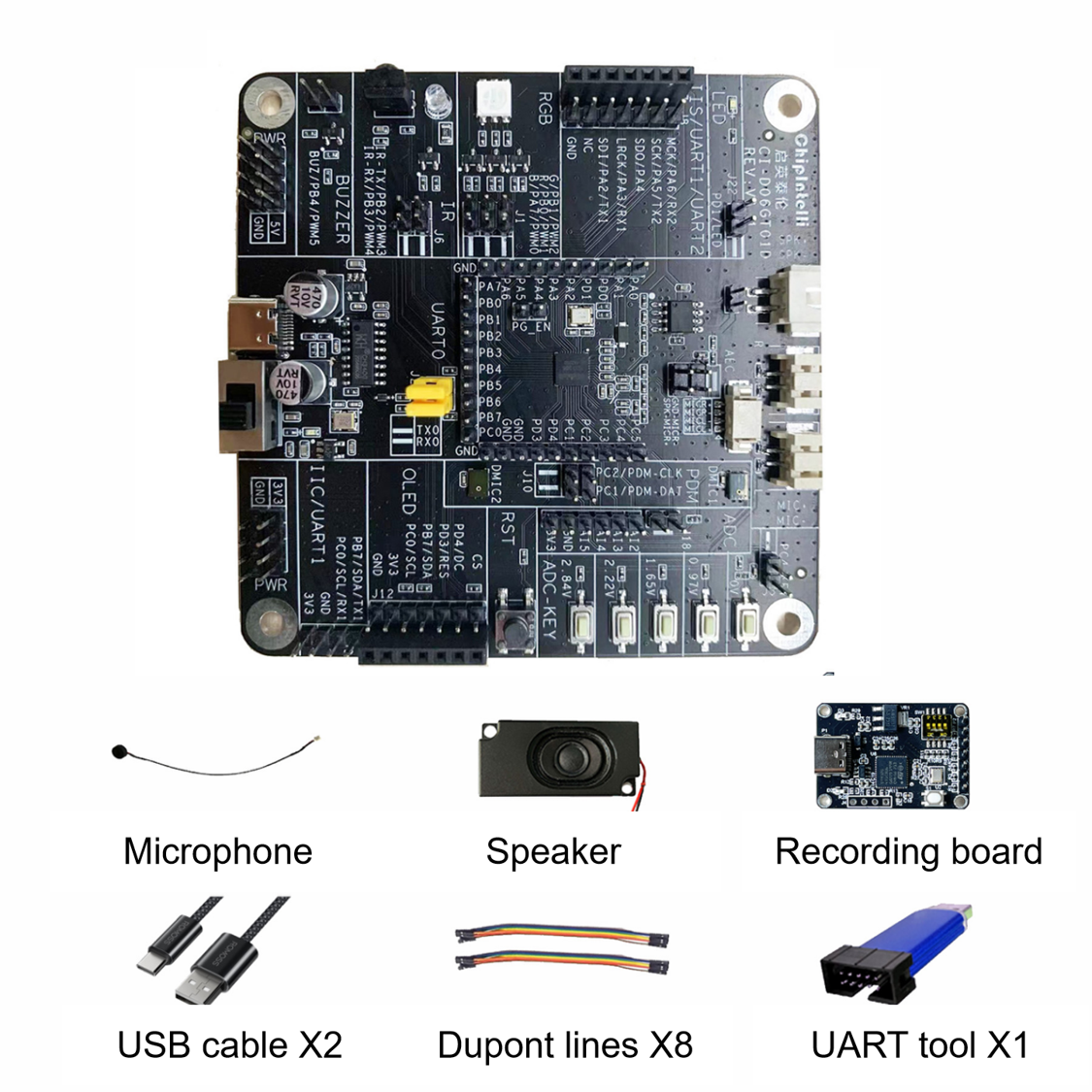
Development Board Accessories
The CI-D06GT01D package includes the following accessories:
| Name | Purpose | Quantity | Standard |
|---|---|---|---|
| CI-D06GT01D | Development Board | 1 | ✓ |
| Microphone | Audio Capture | 2 | ✓ |
| Speaker | Voice Broadcast | 1 | ✓ |
| UART Debug Tool | Debug Communication | 1 | ✓ |
| TYPE-C Cable | Firmware Flashing USB Power |
2 | ✓ |
| Audio Capture Board | Development Debugging | 1 | ✓ |
| Dupont Wire | Development Debugging | 8 | ✓ |
Application Example
The CI-D06GT01D development board kit comes with factory firmware pre-flashed by default, enabling standard voice recognition and wake-up.
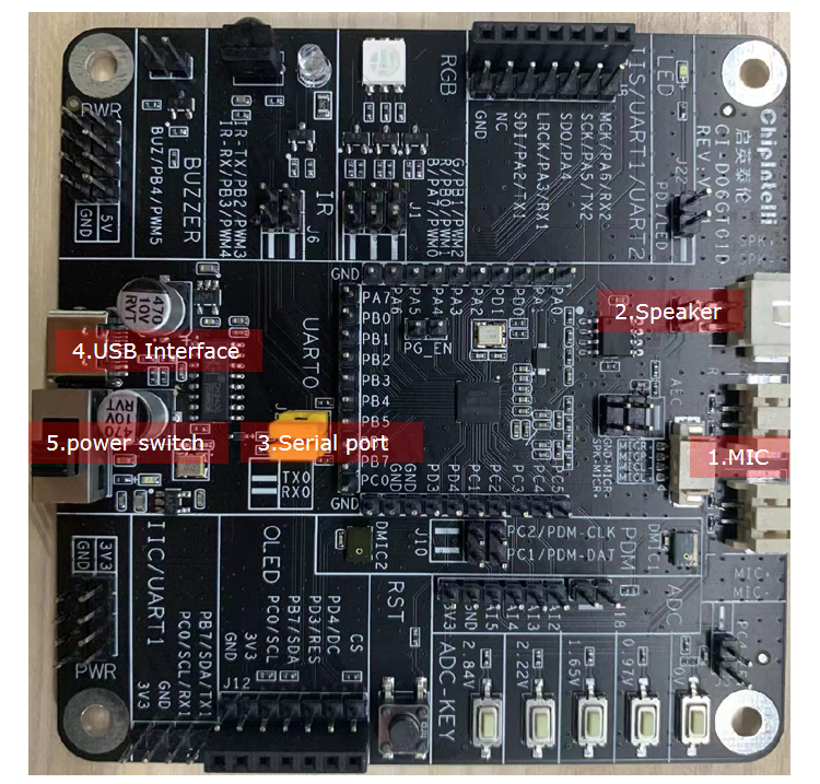
Connect the development board as follows and turn on the power (switch near USB port is ON) to hear the standard firmware voice broadcast.
- Connect the TYPE-C USB to the USB interface marked as 4 in Figure 3;
- Connect two microphones to the analog microphone interface marked as 1 in Figure 3; (Note microphone positive and negative polarity, microphone red wire represents positive, black wire represents negative, connect red wire to MIC+ and black wire to MIC- according to the silkscreen);
- Connect the speaker to the speaker interface marked as 2 in Figure 3;
- Short the UART0 position marked as 3 in Figure 3.
Note: The default standard firmware of the development board applies dual microphones, so both microphones need to be connected in development.
Standard Development Board Command Words and Corresponding Voice Prompts
The standard development board comes with pre-installed standard firmware. To use it, first say the wake word “Hello Jenny”, after hearing the response “what can i do for you”, you can say other command words. When you hear “I am leaving, call me later”, please say “hello jenny” again to wake it up.
The following table lists the command words corresponding to our standard firmware.
Note: Check the stickers on the development board for the corresponding command words

Firmware Flashing
After connecting the development board kit as described in the application example, follow these steps to flash and test:
- Connect one end of the TYPE-C cable to the computer’s USB port and the other end to the development board’s USB port;
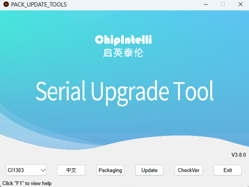
- Open the firmware flashing tool
PACK_UPDATE_TOOL.exe(this tool can be found in the SDK development package CI130X_SDK\tools directory), select the corresponding model according to the chip, click the firmwareupdatebutton, select the prepared firmware file, and find the corresponding serial port number assigned by the computer to the USB to UART tool. After preparations are complete, enter programming mode by instant power-on of the chip, at which time the firmware can be downloaded. If the USB to UART tool cannot be recognized on the computer, please install the corresponding driver on the computer.
- Turn on the power switch, when you see the light on the development board turn on, it indicates power is connected, and the firmware starts downloading.
- Wait for the firmware download to complete, then power on again. After power on, you will hear “Welcome to use Smart fan, you can use hello jenny to wake me up”. At this time, when you say “hello jenny”, you will hear the development board broadcast “what can i do for you”, which means the standard firmware has been downloaded successfully and the development board is working normally;
- If there are any abnormalities, please contact our technical staff for support.
Application Notes
For development board SDK debugging methods, users can refer to the document 《CI13XX Series Chip SDK》, which contains detailed usage instructions for how to do SDK debugging on this development board.