Universal Asynchronous Receiver/Transmitter (UART)
1. Introduction
- UART is a general‑purpose asynchronous serial communication interface that supports full‑duplex transmission between two devices. There is no shared clock between the receiver and transmitter; therefore, both devices must be configured with the same baud rate and frame format for reliable communication.
- CI13XX supports three UART controllers: UART0, UART1, and UART2.
2. Features
- Supports standard UART protocol. A frame consists of Start bit, Data bits (configurable length), optional Parity bit, and Stop bit(s) (configurable width). Baud rate is configurable.
- When idle, the UART line remains at logic high level.
- Start bit: Marks the beginning of a frame; each frame starts with one bit‑width low level to notify the receiver that transmission has started.
- Data bits: Configurable to 5–8 bits via
UART_LCRConfig(commonly 8 bits). Bit order is LSB first then MSB last. - Parity bit: Enable/disable parity and select odd/even via
UART_LCRConfig. When enabled, parity checks detect errors after the data bits. - Stop bit(s): Marks end of frame; logic high. Configurable to 1, 1.5, or 2 bits via
UART_LCRConfig.
3. Timing Diagrams
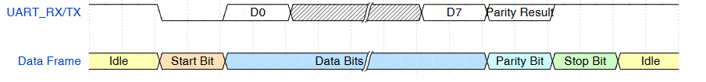
- Timing for one UART frame (8 data bits, parity, 1 stop bit):
 {:.center }
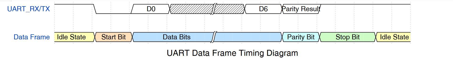
- Timing for one UART frame (7 data bits, parity, 1.5 stop bits):
 {:.center }
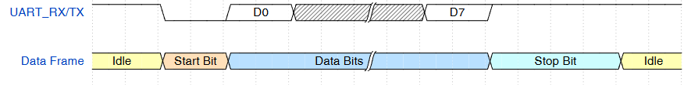
- Timing for one UART frame (8 data bits, no parity, 2 stop bits):
 {:.center }
- A higher baud rate increases throughput but also susceptibility to noise and bit errors. Ensure both devices’ UART hardware supports the selected baud rate; excessively high rates may cause unstable communication.
- Maximum supported baud rate is 3 Mbps; configure via
UART_BAUDRATEConfig.
4. API List
| Function Name | Description |
|---|---|
| UARTPollingConfig | Initialize UART in polling mode |
| UARTInterruptConfig | Initialize UART in interrupt mode |
| UARTDMAConfig | Initialize UART in DMA mode |
| UART_IntMaskConfig | Configure UART interrupt mask |
| UART_IntClear | Clear UART interrupt flags |
| UartPollingReceiveData | Receive one byte (polling) |
| UartPollingSenddata | Send one byte (polling) |
| UART_LCRConfig | Configure parity, stop, and data bits |
| UART_BAUDRATEConfig | Configure baud rate |
5. Examples
- Modify UART pin configuration in board file (e.g.,
CI-D06GT01D.c):
/* UART pin initialization interface */
void pad_config_for_uart(UART_TypeDef *UARTx)
{
    if (UARTx == UART0)
    {
        dpmu_set_io_reuse(PB5,SECOND_FUNCTION);
        dpmu_set_io_reuse(PB6,SECOND_FUNCTION);
        #if 1
        // If external pull-ups to 5V are present, configure as follows
        dpmu_set_io_open_drain(PB5,ENABLE);      // Enable open-drain; supports external 5V pull-up
        dpmu_set_io_open_drain(PB6,ENABLE);      // Enable open-drain; supports external 5V pull-up
        dpmu_set_io_pull(PB5,DPMU_IO_PULL_DISABLE);   // Disable internal pull-up
        dpmu_set_io_pull(PB6,DPMU_IO_PULL_DISABLE);   // Disable internal pull-up
        #else
        // If no external pull-ups
        dpmu_set_io_pull(PB5,DPMU_IO_PULL_UP);   // Enable pull-up
        dpmu_set_io_pull(PB6,DPMU_IO_PULL_UP);   // Enable pull-up
        #endif
    }
    else if (UARTx == UART1)
    {
        dpmu_set_io_reuse(PB7,SECOND_FUNCTION);
        dpmu_set_io_reuse(PC0,SECOND_FUNCTION);
        dpmu_set_io_pull(PC0,DPMU_IO_PULL_UP);  // RX requires pull-up
    }
    else if (UARTx == UART2)
    {
        dpmu_set_io_reuse(PB1,THIRD_FUNCTION);
        dpmu_set_io_reuse(PB2,THIRD_FUNCTION);
        dpmu_set_io_pull(PB2,DPMU_IO_PULL_UP);  // RX requires pull-up
    }
}
5.1 Polling Mode
- Configure UART0 in polling mode, send and receive data, then verify correctness by comparison:
#include "ci130x_uart.h"

void uart_polling_test(void)
{
    // Initialize send/receive buffers
    unsigned char buf_send[32] = {0x0};
    unsigned char buf_recv[32] = {0x0};
    for(int i = 0;i < 32;i++)
    {
        buf_send[i] = i;
    }

    // Initialize UART0 (polling mode), baud 115200
    UARTPollingConfig(UART0, UART_BaudRate115200);

    // Send data: one byte at a time
    for(int i=0;i<32;i++)
    {
        UartPollingSenddata(UART0,buf_send[i]);
    }

    // Receive data: one byte at a time
    for(int i=0;i<32;i++)
    {
        buf_recv[i] = UartPollingReceiveData(UART0);
    }

    // Compare TX/RX data equality
    for(int i=0;i<32;i++)
    {
        if(buf_send[i] != buf_recv[i])
        {
            mprintf("Comparison of the Data Fail\n");
            break;
        }
    }
    else
    {
        mprintf("Comparison of the Data Successful\n");
    }
}
5.2 Interrupt Mode
- Configure UART0 in interrupt mode; use polling to send and interrupt to receive; then verify by comparison:
#include "ci130x_uart.h"
unsigned char buf_send[32] = {0x0};
unsigned char buf_recv[32] = {0x0};

void uart_interrupt_test(void)
{
    // Initialize UART0 (interrupt mode)
    UARTInterruptConfig(UART0,UART_BaudRate115200);

    //initialize send/receive data array
    for(int i = 0;i < 32;i++)
    {
        buf_send[i] = i;
    }

    //send data: one byte at a time
    for(int i=0;i<32;i++)
    {
        UartPollingSenddata(UART0,buf_send[i]);
    }

    //compare received and sent data
    for(int i = 0;i < 32;i++)
    {
        if(buf_send[i] != buf_recv[i])
        {
            mprintf("Comparison of the Data Fail\n");
            break;
        }
    }
    else
    {
        mprintf("Comparison of the Data Successful\n");
    }
}
- UART interrupt service routine:
#include "ci130x_uart.h"
extern unsigned char buf_recv[32];
int length = 0;

/* UART interrupt service routine */
void UART0_IRQHandler(void)
{
    /* TX */
    if (UART0->UARTMIS & (1UL << UART_TXInt))
    {
        ;
    }
    /* RX */
    if (UART0->UARTMIS & (1UL << UART_RXInt))
    {
        //here FIFO DATA must be read out
        buf_recv[length] = UartPollingReceiveData(UART0);
        length ++;
    }
    UART_IntClear(UART0,UART_AllInt);
}
5.2 DMA Mode
- Configure UART0 in DMA mode to send/receive data, then verify by comparison:
#include "ci130x_uart.h"
#include "ci130x_dma.h"
unsigned char buf_send[2048] = {0};
unsigned char buf_recv[2048] = {0};

void uart_dma_test(void)
{
    // Configure DMA transfer width
    TRANSFERWIDTHx trans_width = TRANSFERWIDTH_8b;
    // DMA transfer length (bytes)
    int bytesize = 2048;

    scu_set_dma_mode(DMAINT_SEL_CHANNELALL);

    //initialize send/receive data array
    for(int i = 0;i < bytesize;i++)
    {
        buf_send[i] = i;
    }

    // Initialize UART0 (DMA mode)
    UARTDMAConfig(UART0, UART_BaudRate115200);

    // DMA RX
    DMAC_M2P_P2M_advance_config(DMACChannel0,
                            DMAC_Peripherals_UART0_RX,
                            P2M_DMA,
                            UART0_DMA_ADDR,
                            (unsigned int)buf_recv,
                            bytesize,
                            trans_width,
                            BURSTSIZE1,
                            DMAC_AHBMaster1);

    // DMA TX
    DMAC_M2P_P2M_advance_config(DMACChannel1,
                            DMAC_Peripherals_UART0_TX,
                            M2P_DMA,
                            (unsigned int)buf_send,
                            UART0_DMA_ADDR,
                            bytesize,
                            trans_width,
                            BURSTSIZE1,
                            DMAC_AHBMaster1);

    // Wait for DMA Channel1 TX complete
    if(RETURN_ERR == wait_dma_translate_flag(DMACChannel1,0xffffff))
    {
        mprintf("send dma irq err\n");
    }

    // Wait for DMA Channel0 RX complete
    if(RETURN_ERR == wait_dma_translate_flag(DMACChannel0,0xffffff))
    {
        mprintf("recv dma irq err\n");
    }

    //compare received and sent data
    for(int i = 0;i < bytesize;i++)
    {
        if(buf_send[i] != buf_recv[i])
        {
            mprintf("Comparison of the Data Fail\n");
            break;
        }
    }
    else
    {
        mprintf("Comparison of the Data Successful\n");
    }
}
- DMA interrupt service routine:
#include "ci130x_uart.h"
#include "ci130x_dma.h"

void DMA_IRQHandler(void)
{
    int reg = DMAC->DMACIntTCStatus;
    if (reg & (1 << DMACChannel0))
    {
        CALL_CALLBACK(g_dma_channel0_callback);
    }
    if (reg & (1 << DMACChannel1))
    {
        CALL_CALLBACK(g_dma_channel1_callback);
    }
    DMAC->DMACIntTCClear = reg;
}
6. Others
- Common baud rate ranges
| UARTx | Baud Rate (bps) |
|---|---|
| UART0 | 2400, 4800, 9600, 1920038400, 57600, 115200230400, 380400, 460800921600, 1M, 2M, 3M |
| UART1 | 2400, 4800, 9600, 1920038400, 57600, 115200230400, 380400, 460800921600, 1M, 2M, 3M |
| UART2 | 2400, 4800, 9600, 1920038400, 57600, 115200230400, 380400, 460800921600, 1M, 2M, 3M |