Offline Programming Tool User Manual
-
This document serves as the user manual for our offline programming tool (hereinafter referred to as the programmer). The offline programmer is a self-developed module board with onboard TF card, buttons, power switch, and other hardware. Simply connect the target board to the offline programmer, power it on, and you can update the firmware for other module boards without needing a computer. To purchase the offline programmer, please click ☞Sample Purchase or contact our sales team.
-
The main function of this tool is to copy configuration files to a TF card, insert the TF card into the programmer’s card slot, connect the target board’s UART0 to the programmer’s UART2 interface, and power the programmer with an adapter. Following the voice prompts (if a speaker is connected to the programmer), press the “Upgrade” button after the programmer passes self-test and enters the upgrade page to update the firmware of the target board.
-
Compared to PC serial port programming tools, the offline programmer features a graphical interface that can confirm the CRC checksum of the firmware, count successful programming attempts and failure reasons, and provide audio prompts (if a speaker is connected). It doesn’t require a computer and can be powered by a USB power bank or adapter, making it portable and usable anywhere.
-
The following sections provide detailed explanations on environment setup, upgrade process, TF card data, upgrade examples, and common troubleshooting.
1. Environment Setup
1.1. Upgrade Devices
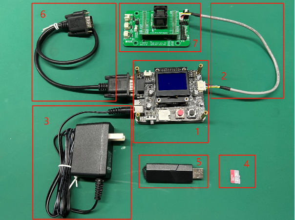
- The following table describes the hardware components required for the offline programmer, including quantities and acquisition methods.
| No. | Name | Qty | Description |
|---|---|---|---|
| 1 | Offline Programmer Mainboard (with Display) | 1 | Provided by Chipintelli (with relevant documentation) |
| 2 | Programming Cable | 1 | Provided by Chipintelli, used for powering the CI13XX chip and serial communication |
| 3 | Power Adapter | 1 | Provided by Chipintelli, used to power the programmer mainboard |
| 4 | TF Card | 1 | Provided by Chipintelli or self-purchased, used to store firmware, configuration files, and log files |
| 5 | TF Card Reader | 1 | Provided by Chipintelli or self-purchased, used to read and modify TF card contents |
| 6 | Machine Communication Cable | 1 | Provided by Chipintelli, used for communication between the programmer and the machine for batch programming |
| 7 | SOCKET Adapter Board and Socket | 1 | Provided by Chipintelli (requires separate purchase) |
1.2. Offline Upgrade Hardware Description
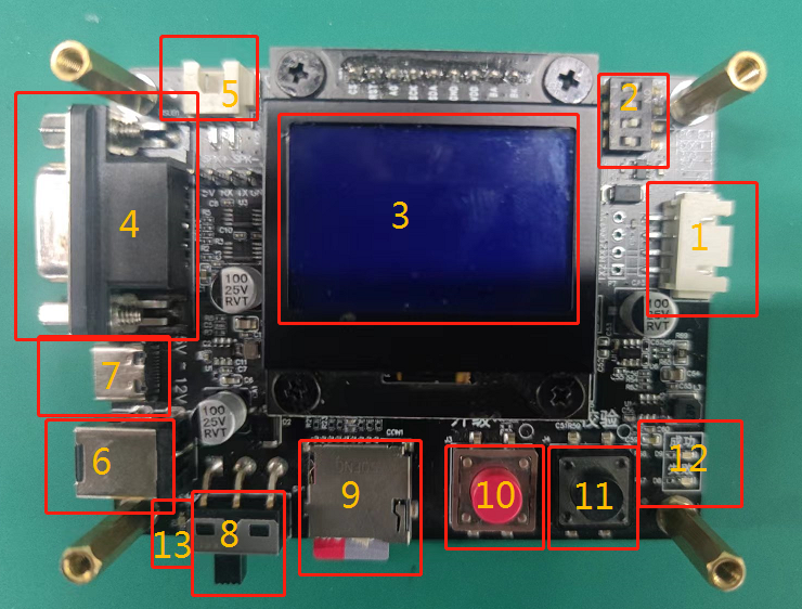
- The table below provides a detailed description of the programmer mainboard.
| No. | Name | Description |
|---|---|---|
| 1 | Chip Programming Interface | Connects to the 4-pin cable of the socket adapter board |
| 2 | DIP Switch | Used to control the programmer’s operating mode |
| 3 | Display | LCD screen showing programming information |
| 4 | Machine Communication Port | Port for machine control communication |
| 5 | Speaker Interface | Speaker connection (connect a speaker if needed) |
| 6 | Power Adapter Interface | 12V power adapter interface |
| 7 | TYPE-C Interface (Power Only) | TYPE C interface |
| 8 | Power Switch | Controls power to the programmer |
| 9 | TF Card Slot | TF card interface |
| 10 | Programming Button | Upgrade button (press to start manual upgrade, long press to flip the screen) |
| 11 | Verify Button | Verification button (press to verify the upgraded firmware) |
| 12 | Programming Status LED | Indicates whether chip programming/verification was successful |
| 13 | Power LED | Indicates if the programmer is powered on |
1.3. DIP Switch Settings
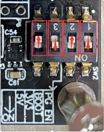
- Before use, ensure that DIP switches 1 and 3 are set to ON, and DIP switches 2 and 4 are set to OFF as shown in the figure below. If you need to change the DIP switch settings for the programmer to function properly, please contact Chipintelli. Do not modify the DIP switch settings without authorization.
1.4. Upgrade Framework
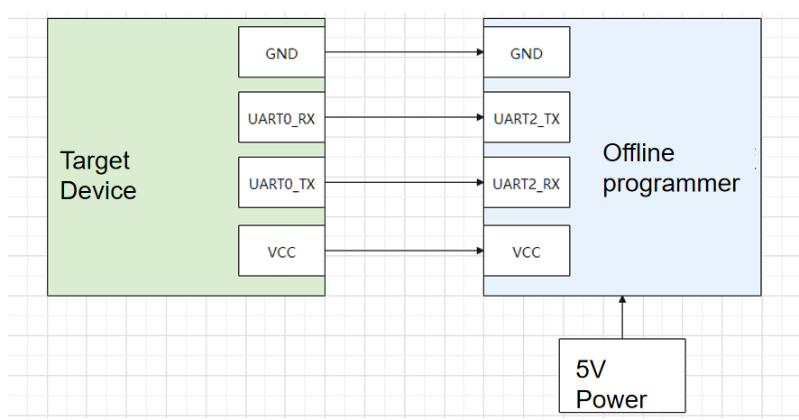
- The diagram below shows the connection between the offline programmer and the target device, including the detailed pin correspondence and power requirements.
1.5. Upgrade Environment
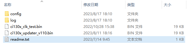
- The firmware, configuration information, and programming logs required by this programmer are all stored on the TF card. A typical TF card root directory is shown in the figure below.
- To program the offline upgrade mainboard firmware: Use the serial port programming tool provided by Chipintelli (for quick start, please refer to ☞Serial Port Debugging Tool User Manual) to update the firmware of the offline upgrade mainboard. Use a card reader to copy the required upgrade files to an empty TF card. Before powering on the board, insert the TF card into the card slot.
2. Upgrade Process
- Turn off the programmer and insert the prepared TF card into the TF card slot of the programmer.
- Connect the programming interface: Connect the programmer’s UART2 interface to the target socket or voice module’s UART0 interface, ensuring that 5V is connected to 5V, GND to GND, the programmer’s RX to the module or socket’s TX, and the programmer’s TX to the module or socket’s RX.
- Power the programmer with a 12V power adapter.
- Turn on the power switch and wait for the programmer to self-test. If self-testing fails, refer to the table below to check for errors. During the self-test process, the programmer’s display screen will show the programmer’s firmware version number.
| Error Code | Description |
|---|---|
| E2 | Missing .ini configuration file in TF card |
| E3 | Flash erase failed during self-upgrade |
| E4 | Failed to open self-update firmware |
| E5 | Self-upgrade failed |
| E6 | Failed to add new log file |
| E7 | Dongle initialization failed: Communication error, dongle not detected |
| E8 | Dongle initialization failed: Authentication failed, including communication errors |
| E9 | Dongle initialization failed: Password query failed, including communication errors |
| E10 | Dongle initialization failed: Usage count query failed, including communication errors |
| E11 | Dongle initialization failed: Maximum usage count query failed, including communication errors |
| E12 | Dongle initialization failed: Usage count exceeded limit |
| E13 | Target firmware is missing version information |
| E14 | Target firmware not found |
| E15 | Incorrect chip model selected, configuration does not match target firmware |
| E16 | TF card version is too old |
| E17 | Private file not found |
| E18 | Missing TF card version information |
| E19 | Missing programmer function selection |
| E20 | Programmer function selection error |
- After confirming the socket adapter board is properly connected to the programmer, press the upgrade button (red button on the programmer) to start the programming process. The red and green LEDs on the programmer will start blinking.
- When both LEDs stop blinking, the programming process is complete. If the green LED stays on and the red LED stays off, it indicates successful programming. If the red LED stays on and the green LED stays off, it indicates a programming failure. Please refer to the following table for troubleshooting.
| Error Code | Description | Troubleshooting |
|---|---|---|
| E1 | Current detection failed for target chip | 1. No chip in socket or poor connection; 2. Chip orientation is reversed |
| E2 | ci130x_updater_VXXX.bin not found in TF card | Check if ci130x_updater_VXXX.bin exists in TF card |
| E3 | Target firmware not found in TF card root directory | 1. Verify target firmware exists in TF card root; 2. Check if the firmware name under “[general_firmware_name]” in xxxx.ini exactly matches the firmware filename (case-sensitive, check for extra spaces/symbols and .bin extension); 3. Verify xxxx.ini encoding is correct |
| E4 | Updater download failed | Check hardware connections |
| E5 | Bootloader download failed | Check hardware connections |
| E6 | Partition table 1 download failed | Check hardware connections |
| E7 | Partition table 2 download failed | Check hardware connections |
| E8 | USER1 download failed | Check hardware connections |
| E9 | USER2 download failed | Check hardware connections |
| E10 | ASR download failed | Check hardware connections |
| E11 | DNN download failed | Check hardware connections |
| E12 | USER_FILE download failed | Check hardware connections |
| E13 | VOICE upgrade failed | Check hardware connections |
| E14 | NV erase failed | Check hardware connections |
| E15 | Full chip upgrade failed | 1. Poor communication quality, check wiring; 2. Try reducing high-speed baud rate in configuration file; 3. Hardware flash memory might be defective, further analysis needed |
| E16 | Verification failed | Check hardware connections |
| E17 | Failed to read partition information | Check hardware connections |
| E18 | Partition information verification failed | Check hardware connections |
| E19 | No upgrade request from updater, updater program not running properly | Check hardware connections |
| E20 | Timeout waiting for updater response | Check hardware connections |
| E21 | Updater response error | Check hardware connections |
| E22 | Frequency test failed | Check hardware connections |
| E23 | Frequency test firmware download failed | Check hardware connections |
| E24 | Firmware size exceeds chip FLASH capacity | Adjust NV reserved size to: NV start address + NV reserved size <= chip flash capacity |
| E25 | Frequency calibration exception | Check hardware connections |
| E26 | Dongle initialization failed | Check hardware connections |
| E27 | Dongle authentication failed, including communication errors | Check hardware connections |
| E28 | Dongle usage count reached maximum, including communication errors | Check hardware connections |
| E29 | Failed to increment dongle usage count, including communication errors | Check hardware connections |
| E30 | Failed to query dongle usage count | Check hardware connections |
| E31 | Maximum displayable programming count reached | Check hardware connections |
| E32 | Other errors | Analyze based on actual situation |
3. Sampling Test Method for programed Firmware
- With the programmer powered off, insert the prepared TF card into the TF card slot of the programmer.
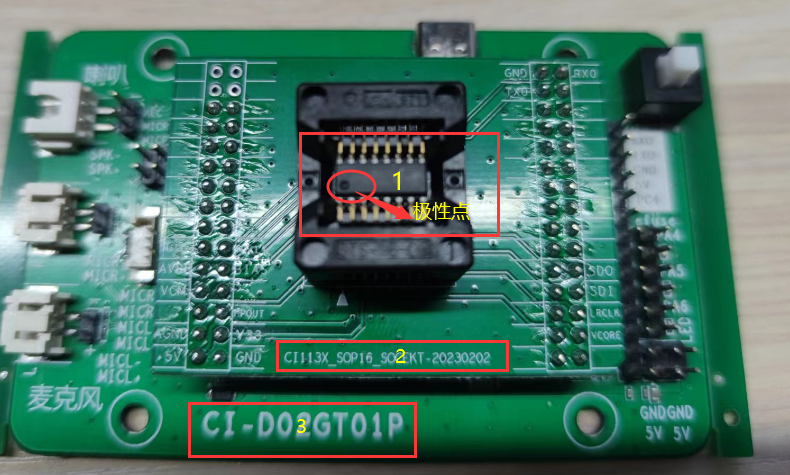
- Press the black frames on both sides of the socket as shown in the figure below, and place the chip to be tested according to the illustration. Pay attention to the polarity mark on the chip and the silkscreen on the socket board. Note: The orientation of the adapter board, socket, and chip should match the direction shown in the picture.
- Connect the programming interface: Connect the programmer’s interface to the target board, ensuring:
- 5V to 5V
- GND to GND
- Programmer RX to module/socket TX
- Programmer TX to module/socket RX
- Connect the 12V power adapter to the programmer.
- Turn on the power switch and wait for the programmer to complete self-test. During self-test, the programmer’s display will show its firmware version.
- Press the verification button (black button on the programmer) to start verification. The red and green LEDs on the programmer will start blinking.
- When both LEDs stop blinking, the verification is complete. If the green LED stays on and the red LED stays off, verification is successful. If the red LED stays on and the green LED stays off, verification has failed, indicating defective chips in this batch that need to be reprogrammed.
- Important: In addition to first-article inspection, sample 0.3% of chips from each batch for verification.
4. Programmer Firmware Update
The pins used for the programmer’s own firmware update are shown in the figure below.
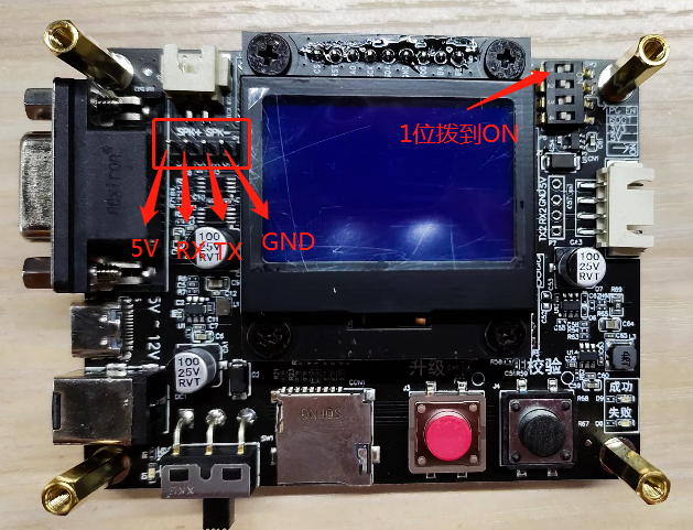
- Connect the serial debug tool to the pins marked in the red box in the figure below:
- Programmer 5V to serial tool 5V
- Programmer GND to serial tool GND
- Programmer TX to serial tool RX
- Programmer RX to serial tool TX
- Set the topmost DIP switch (position 1) to ON according to the figure above. (Remember to return it to the original position after testing)
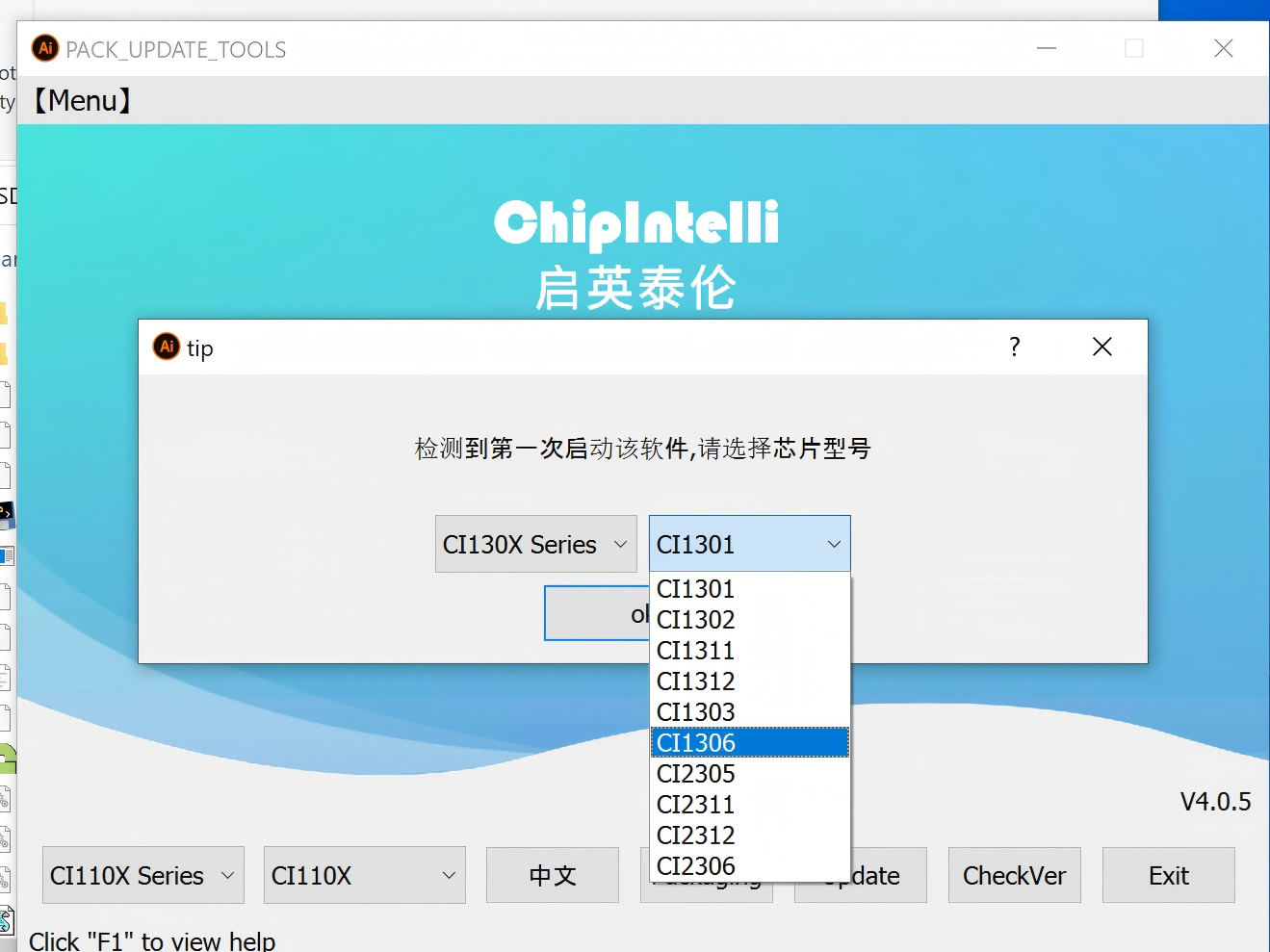
- Open the PC upgrade tool, select CI13XX, click [OK], then click [Firmware Update], and follow the sequence shown in the figure below. (If the PC upgrade tool version is too old, the interface may be slightly different. Please contact us for the latest PC upgrade tool if needed)
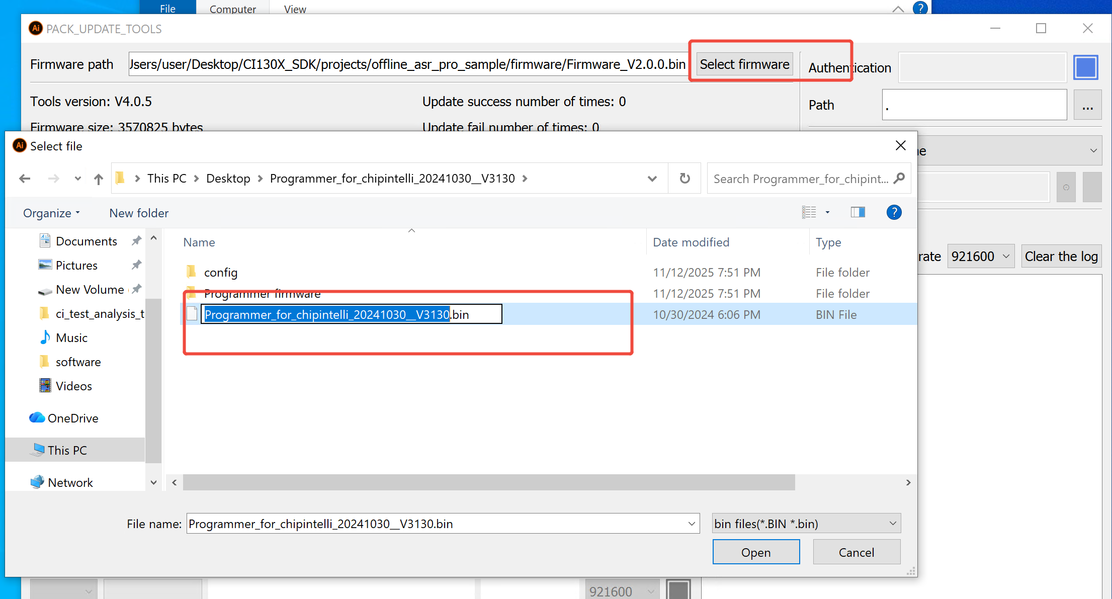
- Click [Select Firmware] to choose the programmer firmware file from the release package. Double-click the firmware file named “Programmer_for_CI130x_20230526_VXXX.bin” (the name may vary with different firmware versions, please adjust according to the actual file name). The interface will be as shown in the figure below.
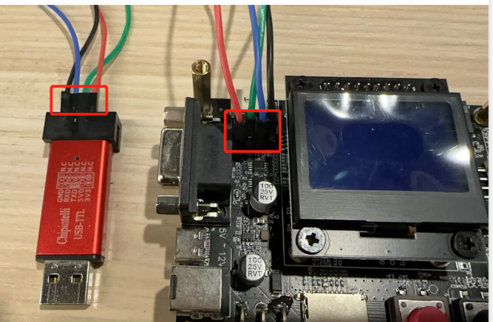
- Insert the red USB-to-TTL Tool shown in the figure below into your computer’s USB port. A new COM port (e.g., COM3, the number may vary on different computers) will appear in the upgrade tool. Check the box in the rightmost column of the newly added serial port.
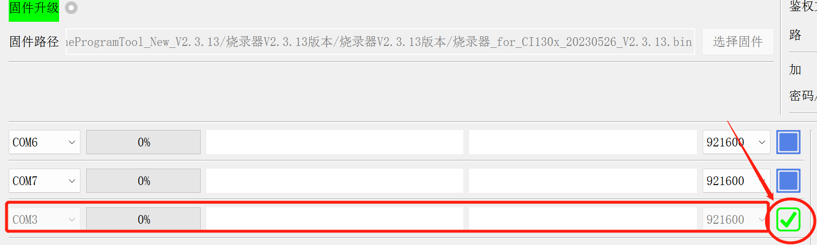
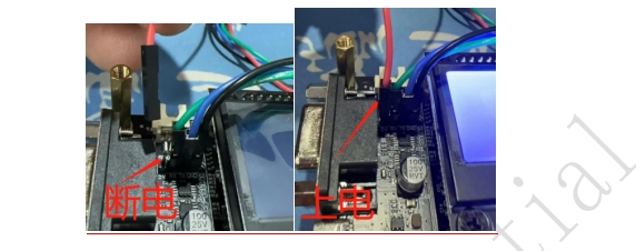
- After confirming the serial port is checked, first disconnect the 5V power (red DuPont wire) from the programmer (as shown in the left figure below), then reconnect it (as shown in the right figure below). The programmer will enter programming mode. The progress bar in the red box in Figure 5-7 will update until it reaches 100%. When the progress bar stops updating, it indicates the programmer firmware update is complete (the entire update process takes 5-30 seconds). If not, repeat the programmer update process.
- After the PC upgrade tool completes the programming process (the status will show “device:update success”), click the selection box in the figure above again to uncheck it.
- Power off the programmer, then power it back on. The display will show the programmer’s firmware version. Verify that the version number matches the one you just updated to.
5. Firmware Checksum Verification Method
5.1 Developer Generates Firmware Checksum
- Double-click to run CRC-32.exe
- Select [File] > [Open] and choose the firmware file for checksum calculation
- The checksum will be displayed as an 8-digit hexadecimal number after calculation. Copy the generated checksum to a TXT file and provide it to the programming operator along with the work order.
5.2 Operator Verifies Firmware Checksum
The programmer supports displaying the checksum of the firmware to be programmed. After power-on self-test completes, the checksum will be shown at the top of the display as shown below:
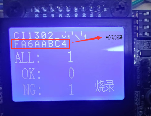
Note: Before batch programming, operators must verify that the checksum on each programmer matches the one provided in the work order.
6. Programmer Video Tutorials
Manual Programming Video:
Automatic Programming Video: