CI-F16XGS02J Module Datasheet
Module Introduction
Overview
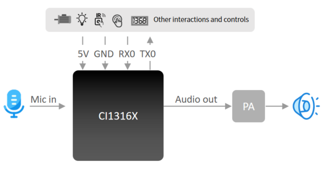
The CI-F16GS02J is a general-purpose, portable, low-power, high-performance voice recognition module designed for cost-effective offline voice applications. The module features the CI13161/CI13162 as its main chip and supports up to 300 offline voice commands (the exact number varies by model).
Key Features:
- Compact size: 30mm × 40mm
- Operating voltage: 3.6V-5.5V
- Onboard power amplifier
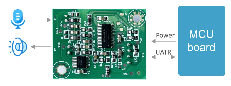
- Integrated microphone input, speaker output, 5V power supply, and UART interface
- Plug-and-play operation with microphone and speaker connections
- Direct connection to host control board via UART or GPIO control without soldering
- Two 3.5mm mounting holes for easy installation and fixation
Technical Highlights: * The main chip supports offline neural network computation and single-microphone noise reduction enhancement * 360° omnidirectional sound pickup with environmental noise suppression for accurate voice recognition in noisy environments * Offline voice recognition with no network dependency, low latency, and high performance * Achieves over 97% recognition accuracy with up to 10-meter recognition range * Ultra-fast response time as quick as 0.2 seconds * Suitable for products with energy efficiency requirements and battery-powered devices * Industrial-grade components ensure high reliability
| Module Type | Up to 100 Local Commands | Up to 300 Local Commands |
|---|---|---|
| Single-Mic Offline Voice Module with Connector | CI-F161GS02J | CI-F162GS02J |
Main Chip Introduction
The CI13161 and CI13162 are dedicated AI chips for voice processing, supporting local voice recognition in multiple global languages including Chinese, English, and Japanese. They are widely used in home appliances, lighting, toys, wearables, industrial, automotive, and other product fields for voice interaction, control, and various intelligent voice solutions.
These chips integrate Chipintelli’s self-developed Brain Neural Network Processor (BNPU V3.5) and CPU core, with a system frequency up to 210MHz. They feature 288KB SRAM, integrated PMU power management unit, RC oscillator, single-channel high-performance low-power Audio Codec, and multiple peripheral control interfaces including UART, I2C, IIS, PWM, GPIO, and PDM. The chips require minimal external components (resistors, capacitors) to implement various intelligent voice product hardware solutions, offering excellent cost performance.
For more detailed information about CI13161 and CI13162 chips, please visit:
☞CI13161&CI13162 Chip Datasheet
Application Scenarios
CI-F162GS02J module supports up to 300 offline voice recognition commands, suitable for products with limited command requirements, such as electric fans, heating desks, drying racks, small household appliances, toys, and lighting.

Module Features
Feature List
The module’s features are described in Table 2 below:
Module Hardware Interface Definition
This module includes the following functional interfaces:
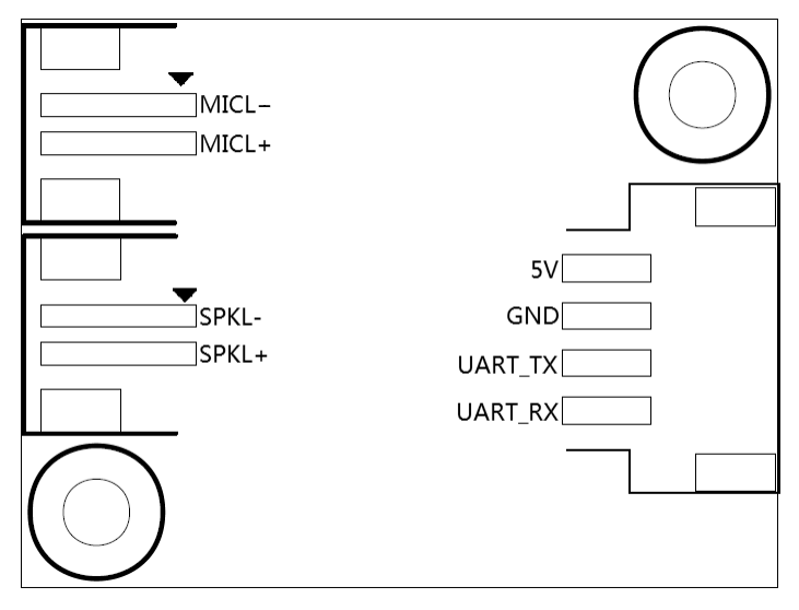
- Dual-wire Single Microphone Interface: Uses a 2.0mm pitch female connector. For optimal voice recognition performance, it is recommended to use a microphone with a sensitivity of -32±3dB and signal-to-noise ratio ≥65dB. Click ☞Reference Microphone Devices for more information.
- Dual-wire Single Speaker Interface: Uses a 2.5mm pitch female connector. For optimal audio output quality, it is recommended to use a speaker with an acoustic chamber. Click ☞Reference Speaker Devices for more information.
- Power Supply and UART Interface: Uses a 2.5mm pitch female connector with 4 pins. Refer to Figure 6 for the pin sequence. The UART pins in this interface can also be configured as GPIO pins.
The functional description of all external pins is shown in Table 2:
| Pin No. | Pin Name | I/O Type | I/O Drive Capability | Default Power-on State | Function Definition |
|---|---|---|---|---|---|
| 1 | 5V | P | - | - | 5V Power Supply |
| 2 | GND | P | - | - | Ground |
| 3 | UART_TX | IO, T+U | 4mA | IN, T+U | 1.UART0_TX 2.PB5 |
| 4 | UART_RX | IO, T+U | 4mA | IN, T+U | 1.UART0_RX 2.PB6 |
| 5 | MICL- | - | - | - | Microphone Negative |
| 6 | MICL+ | - | - | - | Microphone Positive |
| 7 | SKPL- | - | - | - | Speaker Output - |
| 8 | SKPL+ | - | - | - | Speaker Output + |
Symbols used in the above table are defined as follows:
I Input
O Output
IO Bidirectional
P Power or Ground
T+D Tristate plus Pull-down
T+U Tristate plus Pull-up
OUT Power-on defaults to Output mode
IN Power-on defaults to Input mode
Module Electrical Characteristics
| Parameter | Condition | Min | Typ | Max | Unit | Note |
|---|---|---|---|---|---|---|
| Module Supply Voltage | / | 3.6 | 5 | 5.5 | V | NOTE1 |
| Module Current in Playback Mode (Normal Volume) | 4Ω 3W Speaker | / | 65 | / | mA | NOTE2 |
| Module Operating Current | / | / | 35 | / | mA | NOTE3 |
| Idle Current in Quiet Environment | 5V Supply | / | 25 | / | mA | / |
| Chip I/O Interface Voltage | / | 3 | 3.3 | 3.6 | V | / |
| Module UART Interface Voltage | / | 4.5 | 5 | 5.5 | V | / |
NOTE1: 5V is the typical supply voltage for the module. Input voltage exceeding 5.5V may damage the module.
NOTE2: The maximum current in playback mode can reach 250mA. A power supply with 500mA driving capability (2x margin) is recommended for the module.
NOTE3: Typical value is measured in mute state. Maximum value is measured during recognition and playback.
Module Temperature and Humidity Parameters
The temperature and humidity parameters of CI-F16GS02J are shown in Table 4.
| Parameter | Min | Typ | Max | Unit | Note |
|---|---|---|---|---|---|
| Operating Temperature | -40 | 25 | 85 | °C | / |
| Storage Temperature | -40 | 25 | 100 | °C | / |
| Storage Humidity | 0% | / | 5% | RH | / |
Module Application
Power-on and Startup
To use this module, connect the speaker and microphone, then supply 5V power through the power connector. Upon power-up, the module will initialize, and the speaker will play a prompt tone. The UART port will output initialization messages, which can be viewed using a USB-to-UART adapter connected to a computer. Successful module startup is indicated when these messages appear in the serial terminal software. Note that the module’s UART interface operates at 5V logic level, eliminating the need for level conversion when interfacing with other 5V systems.
The power amplifier on the module is powered by a 5V supply. The power supply must provide a rated current of 500mA with stable output and ripple voltage below 300mV.
Default Command Words
For mass-produced modules, firmware with customer-specified command words is typically pre-loaded before shipment. If no custom commands are specified, the module comes with default firmware containing test command words as shown below:

Default UART Communication Protocol
The module’s default firmware includes a UART communication protocol for host communication. This serial protocol is designed to be extensible with the following features:
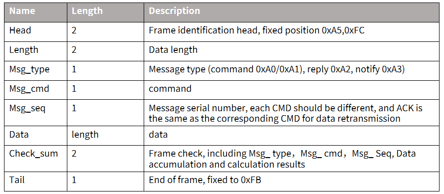
- Complete data packet structure including: header, tail, length, checksum, message type, and sequence number
- Support for variable-length commands for easy expansion
- Multiple message types (commands, notifications, responses)
- Configurable command messages with ACK responses (notifications do not require ACK)
- Compatible message format with bootloader upgrade protocol (distinguished by header)
- Default baud rate: 9600 bps
- Note: The module only provides the UART0 interface, which is by default configured as a print output interface. To use UART0 for the serial protocol interface, code modifications are required as described in the ☞CI13LC Series Chip SDK UART protocol documentation.
- Supported commands include: query protocol version, query system version, set volume (volume levels defined in user_config.h), play local prompt tones, reset command, etc. The protocol format is shown below:
Example 1:
Analysis of A5 FC 07 00 A0 91 18 01 55 E0 01 00 00 1B 9B 02 FB:
A5 FC: Header
07 00: 7 bytes of valid data
A0: Command word information
91: Command code 0x91 (command word data)
18: Packet sequence number (increments with each transmission)
01 55 E0 01 00 00: Unique data for the current command word
1B: Command word threshold
9B 02: Checksum
FB: End marker
Note: If only the command word and threshold are needed, focus on the 7 bytes of valid data (highlighted in blue).
Example 2:
Analysis of A5 FC 02 00 A3 9A 17 00 B1 05 02 FB:
A5 FC: Header
02 00: 2 bytes of valid data
A3: Notification data
9A: Command code 0x9A (voice module state change)
17: Packet sequence number
00 B1: Valid data (indicates wake-up state)
05 02: Checksum
FB: End marker
Note: This is notification data, and users can choose to utilize this information as needed.
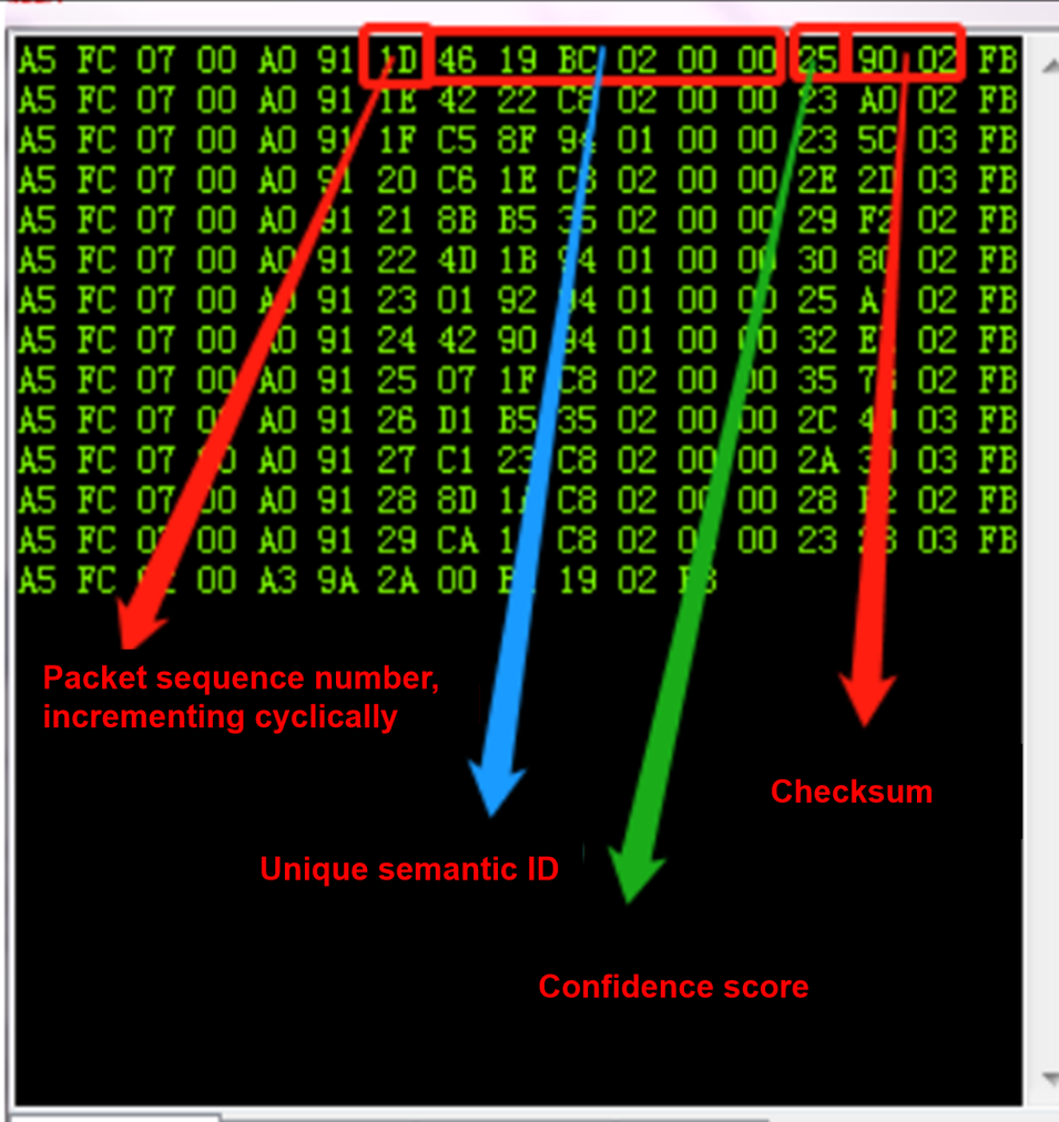
For more detailed protocol parsing, please refer to the UART protocol section in the ☞CI13LC Series Chip SDK. Below is a reference screenshot of protocol data:
Software Development
The default firmware included with the module is primarily for initial user experience. For software development, users need to register and log in to the Chipintelli AI Speech Development Platform (https://aiplatform.Chipintelli.com) for rapid voice firmware development. The platform’s “Development Resources” section provides access to SDKs and related hardware documentation.
New users are recommended to start with the Beginner’s Guide to understand the development workflow. Video tutorials are also available in the Documentation Center for various solutions and SDK development.
Key development resources include: * SDK Development Package Downloads * Model Development (Language Model + Acoustic Model) * Speech Synthesis * Command Word Mapping with Audio Files * Firmware Packaging
For detailed development procedures, please refer to the ☞CI13LC Series Chip SDK.
Firmware flashing
Preparation
Before flashing firmware, prepare the following items:
- Module to be programmed
- USB-to-UART adapter
- Firmware flashing tool (pack_update_tool.exe)
- Firmware file (*.bin format)
- 2.0mm pitch microphone
- 2.5mm pitch speaker
- DuPont wires
flashing Procedure
-
Connect Module to USB-to-UART Adapter - Connect TX, RX, and GND from the USB-to-UART adapter to RX, TX, and GND on the module respectively (note the cross-connection of TX and RX).
-
Power Connection - Connect the 5V power adapter’s positive lead to the module’s 5V pin and negative to GND.
-
Connect Audio Components - Connect the 2.0mm pitch microphone to the MIC interface. - Connect the 2.5mm pitch speaker to the SPK interface.
-
Launch flashing Tool - Run pack_update_tool.exe. - Select the correct COM port. - Set baud rate to 115200. - Click “Open Port.”
-
Select Firmware - Click “Select File” and choose the firmware file (*.bin).
-
Start flashing - Click “Start Download” and wait for completion. - Progress will be shown in the progress bar. - “flash Successful” will be displayed upon completion.
-
Verification - After successful flashing, conduct functional tests by connecting the microphone and speaker. - Power on and verify the module plays the startup prompt. - Test wake word and command word recognition. - If all functions work as expected, the module is functioning correctly.
Troubleshooting Guide
This section addresses common issues and their solutions during module usage.
Firmware flashing Failure
If the module fails to flash firmware, check the following:
-
Connection Sequence - Connect TX, RX, and GND first. - Select the correct COM port in the flashing tool (refer to Figure 13, item 4). - Then apply 5V power.
-
Connection Verification - Verify correct TX/RX connections (cross-connect TX to RX). - Ensure USB-to-UART driver is properly installed. - Confirm correct COM port selection in the flashing tool.
-
Power Supply Check - Measure module voltages: 5V, 3.3V, and 1.1V. - Refer to hardware measurement points in the diagram below. - If voltage or crystal issues are detected, the module may be faulty. - Contact technical support if issues persist after these checks.
No broadcast After Flashing
If there’s No broadcast after flashing:
-
Firmware Compatibility - Verify the firmware matches the module version.
-
Speaker Connection - Check speaker connections and power supply. - Use an oscilloscope to measure audio output test points. - No output may indicate firmware issues. - Distorted output may indicate amplifier hardware problems.
No Command Word Recognition
If the module powers on with audio but doesn’t recognize commands:
-
Microphone Connection - Verify microphone is properly connected. - Check microphone polarity matches board markings.
-
Signal Measurement - Measure MICBIAS pin voltage (should be ~2.8V). - Use an oscilloscope to check microphone input waveform (set to 100mV/div). - Normal signal but no recognition suggests firmware issues. - Abnormal signal indicates potential hardware damage.
Application Notes
ESD Protection
- The module includes ESD protection at the microphone interface.
- Additional ESD devices can be added for products requiring higher protection.
- Always use ESD-safe practices during handling and assembly.
- Wear anti-static wrist straps or gloves during inspection and soldering.
- Include ESD protection on the carrier board connectors.
Important Usage Notes
- Connect microphone, speaker, and power supply correctly.
- Prevent short circuits at test points on the board backside.
- The UART interface uses 5V logic levels.
- For software debugging, add UART print commands in the SDK.
Production, Storage, and Ordering
Production Guidelines
- The module features foolproof connectors for easy assembly.
- Three components connect to their respective terminals: microphone, speaker, and power/communication.
- Use proper ESD protection during assembly.
- Apply appropriate force to ensure secure connections.
- Open vacuum-sealed ESD bags only when ready for assembly.
Storage Conditions
- Store in a non-condensing environment at <40°C/90%RH.
- Moisture Sensitivity Level (MSL): 3
- After opening the vacuum-sealed bag, follow MSL-3 handling procedures.
Ordering Information
| Model | Packaging | Modules per Tray | Modules per Package | Modules per Carton |
|---|---|---|---|---|
| CI-F161GS02J CI-F162GS02J |
Tray + ESD Bag + Carton | 40pcs | 400pcs (10 trays) | 1200pcs (3 packages) |
Purchasing and Technical Support
To purchase samples, visit ☞Sample Purchase or ☞Samples and Bulk Orders for more information.
For technical support, visit the ☞Chipintelli AI Speech Development Platform.