Flash Partition Table
Firmware and Partitions
-
This document provides details on the firmware, partition formats, partition table, and firmware contents.
-
Terminology:
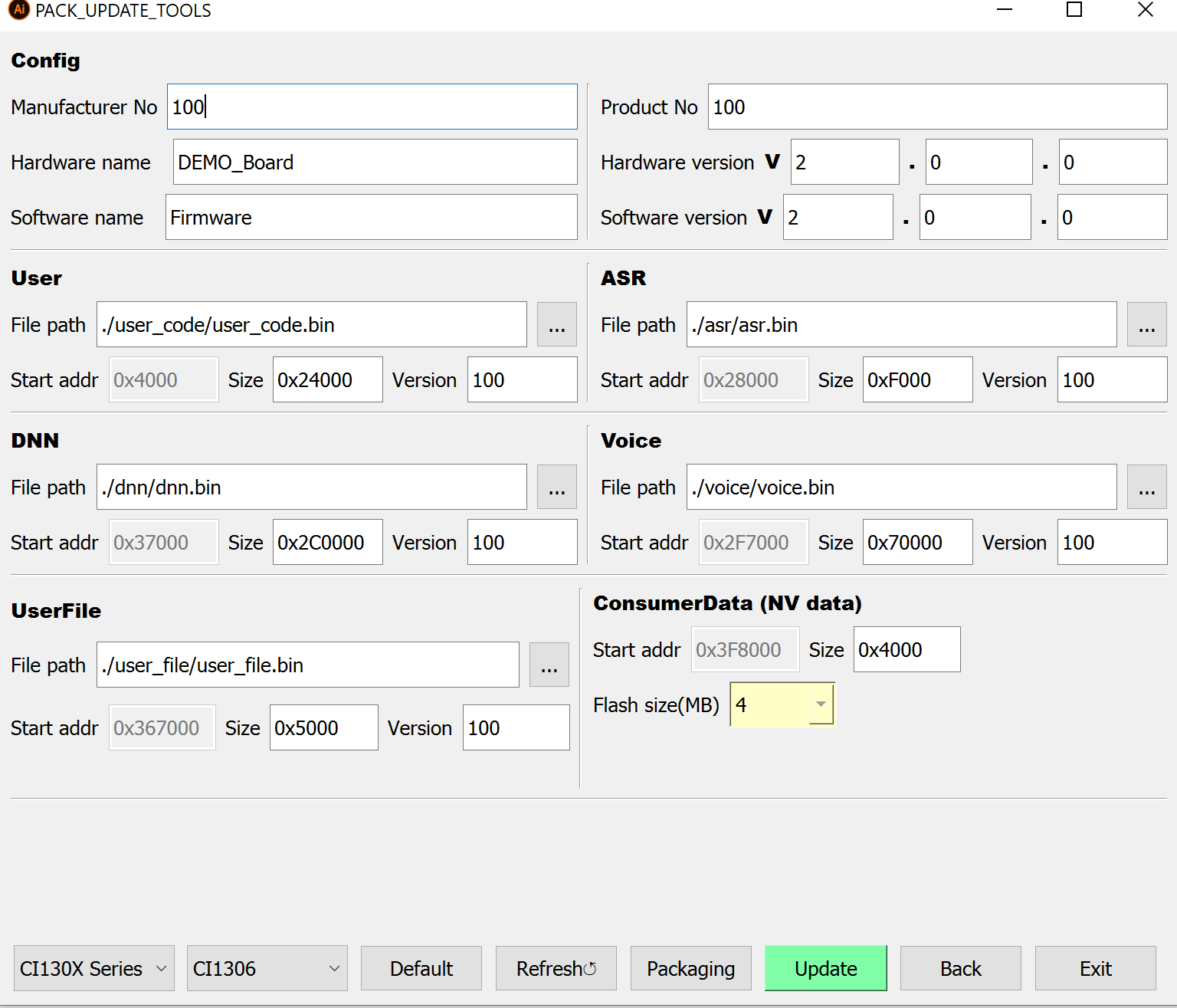
- Firmware: The PC serial packaging/upgrade tool (PACK_UPDATE_TOOL.exe) packages multiple bin files into a Firmware_V2.0.0.bin, which is programmed to Flash and later read by the bootloader and application.
- Partition: A region in the firmware that contains one or more bin files. User‑configurable partitions include User, ASR, DNN, Voice, UserFile, and NV data; others are fixed.
- Firmware version: Different formats exist for different scenarios, e.g., FW_V1, FW_V2, FW_V3; more may be added in the future.
- Partition format: Describes what each partition is and the order of multiple partitions within the firmware.
- Partition table: Contains addresses, sizes, version numbers, and other information for the components of the firmware.
- Bootloader: After power‑up, the chip runs the bootloader at the Flash base, then reads the partition table to parse the application address and other info, and copies the application to SRAM to run.
-
Application: The compiled
user_code.binfile. -
Contents stored in each partition:
| Partition | Contents |
|---|---|
| User | Application image user_code.bin |
| ASR | Language model bundle asr.bin (for ASR) |
| DNN | Acoustic model bundle dnn.bin (for ASR) |
| Voice | Audio prompts bundle voice.bin |
| UserFile | Command table and other files user_file.bin |
| NV data | User-defined data, initialized/managed by the application |
Note
- When packaging the firmware, only the start address and reserved size of NV data are written to the partition table; the NV data contents are not included. Other partitions contain data. During an upgrade, you may choose whether to erase NV data.
1. Firmware
-
For firmware generation, see Quick Start.
-
The firmware is typically named Firmware_V2.0.0.bin, where Firmware is the product name and V2.0.0 is the version.
-
The product name and version can be customized during packaging and are saved in the partition table.
2. Bootloader
-
PACK_UPDATE_TOOL.exe embeds the bootloader for each chip series (bootloader.bin) and places it at firmware address 0 during packaging.
-
Each series has a dedicated bootloader.bin; typically all models in a series share the same bootloader.
-
To support different firmware versions, a series may use different bootloaders, selectable in the tool.
3. Firmware Versions
-
Three firmware versions are supported: FW_V1, FW_V2, FW_V3. Choose which to package via PACK_UPDATE_TOOL.exe.
-
FW_V1: OTA V2 scheme; uses BOOTloaderA (bootloader_a.bin with OTA). User code has no backup. During Wi‑Fi OTA, BOOTloaderA is downloaded to SRAM to perform the upgrade; Wi‑Fi manages per‑partition logic.
- FW_V2: Generic scheme without OTA; bootloader_b.bin (BOOTloaderB) only boots; no other functions; no backup partitions.
-
FW_V3: OTA V3 scheme; uses BOOTloaderB (boot‑only). User code has a backup. During Wi‑Fi OTA, Wi‑Fi mainly pass‑throughs and manages versions; OTA V3 code performs the upgrade.
-
FW_V3 shares the same partition format as FW_V1 but uses a different bootloader.
- FW_V1 and FW_V2 differ in both partition format and bootloader.
4. Partition Formats
-
There are fundamentally two partition formats: Format 1 and Format 2.
-
The packaging UI allows selecting files and configuring reserved sizes; these details are written to the partition table:
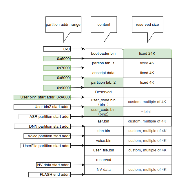
4.1 Format 1
-
FW_V1 and FW_V3 use Format 1; differences from Format 2 are highlighted in green below:
-
Two copies of the partition table and User partition are generated; others have a single copy.
- OTA can modify one User partition to support more scenarios.
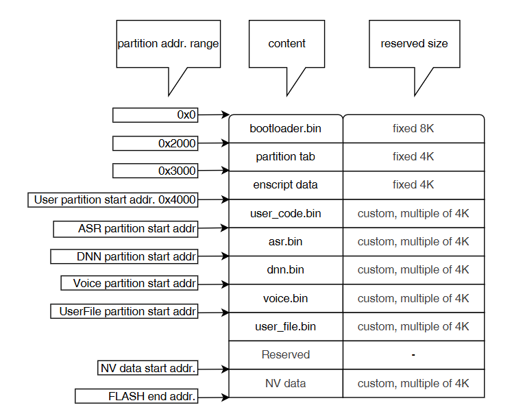
4.2 Format 2
- FW_V2 uses Format 2, the most common; all partitions are single‑copy:
5. Partition Table
-
The partition table provides hardware/software names, the start address and actual size of each partition, version numbers, etc.
-
The application must use the partition table to locate firmware data. The figure below describes each field:
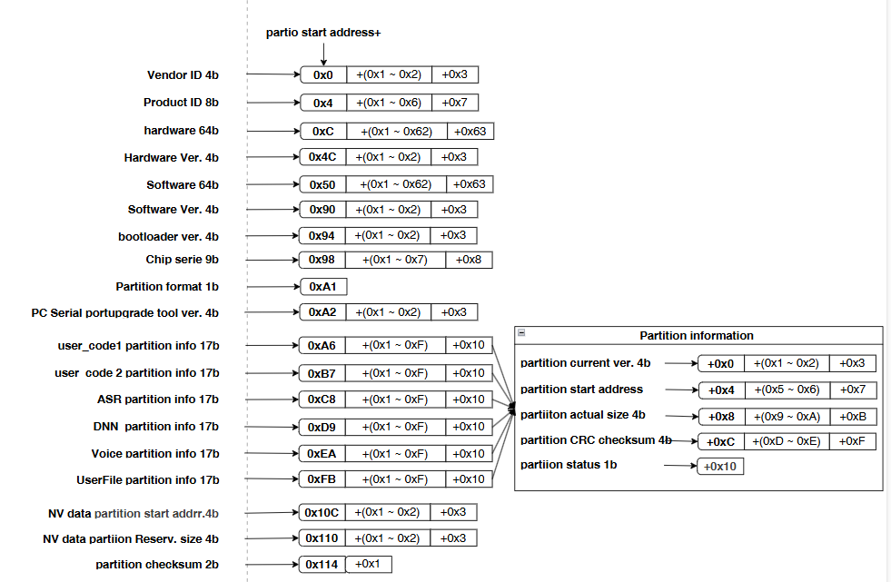
- Example: If the partition table starts at 0x2000, the following decodes as:
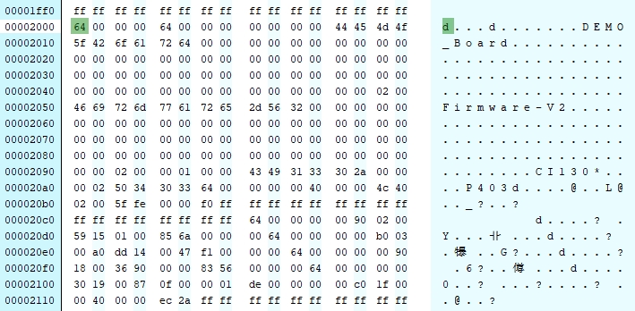
| Field | Address | Value |
|---|---|---|
| Vendor ID | 0x2000 + 0x0 | 0x64 (100) |
| Product ID | 0x2000 + 0x4 | 0x64 (100) |
| Hardware Name | 0x2000 + 0xC | DEMO_Board |
| Hardware Version | 0x2000 + 0x4C | 0x20000 (V2.0.0) |
| Software Name | 0x2000 + 0x50 | Firmware‑V2 |
| Software Version | 0x2000 + 0x90 | 0x20000 (V2.0.0) |
| Bootloader Version | 0x2000 + 0x94 | 0x100 (V0.1.0) |
| Chip Series | 0x2000 + 0x98 | CI130* (CI130X series) |
| Partition Format | 0x2000 + 0xA1 | 0x2 (Format 2) |
| PC Tool Version | 0x2000 + 0xA2 | P403 (PACK_UPDATE_TOOL v4.0.3) |
| user_codec1 current ver | 0x2000 + 0xA6 | 0x64 (100) |
| user_codec1 start addr | 0x2000 + 0xAA | 0x4000 |
| user_codec1 real size | 0x2000 + 0xAE | 0x2404C |
| user_codec1 CRC | 0x2000 + 0xB2 | 0xFE5F |
| user_codec1 status | 0x2000 + 0xB3 | 0xF0 |
| Other partitions ver/CRC/status | - | See user_codec1 parsing |
| user_codec2 start addr | 0x2000 + 0xBB | 0xFFFFFFFF (not present in Format 2) |
| user_codec2 real size | 0x2000 + 0xBF | 0xFFFFFFFF (not present in Format 2) |
| ASR start addr | 0x2000 + 0xCC | 0x29000 |
| ASR real size | 0x2000 + 0xD0 | 0x11559 |
| DNN start addr | 0x2000 + 0xDD | 0x3B000 |
| DNN real size | 0x2000 + 0xE1 | 0x14DDA0 |
| Voice start addr | 0x2000 + 0xEE | 0x189000 |
| Voice real size | 0x2000 + 0xAE | 0x936 |
| UserFile start addr | 0x2000 + 0xFF | 0x193000 |
| UserFile real size | 0x2000 + 0x103 | 0xF87 |
| NV data start addr | 0x2000 + 0xAA | 0x1FC000 |
| NV data reserved size | 0x2000 + 0xAE | 0x2404C |
| Partition table checksum | 0x2000 + 0xAE | 0x4000 |
-
If the partition table is at 0x6000 or 0x8000, decode it using the same method above.
-
You can also read the partition table via code from all three addresses and determine the valid one by checksum:
#include "flash_manage_outside_port.h"
#include "ci_flash_data_info.h"

// Function to compute partition table checksum

extern uint16_t get_partition_list_checksum(partition_table_t *file_config);

#define FILECONFIG_START_ADDR1     (0x2000)   // Partition table 1 start
#define FILECONFIG_START_ADDR2     (0x6000)   // Partition table 2 start
#define FILECONFIG_START_ADDR3     (0x8000)   // Partition table 3 start

partition_table_t partition_table = {0};

void read_partition_table()
{
  // Read table 1 and verify checksum

  post_read_flash((char *)&partition_table,FILECONFIG_START_ADDR1,sizeof(partition_table_t));
  if (partition_table.patitiontablechecksum != get_partition_list_checksum(&partition_table))
  {
      // Table 1 checksum failed; read table 2 and verify

      post_read_flash((char *)&partition_table,FILECONFIG_START_ADDR2,sizeof(partition_table_t));
      if (partition_table.patitiontablechecksum != get_partition_list_checksum(&partition_table))
      {
        // Table 2 checksum failed; read table 3 and verify

        post_read_flash((char *)&partition_table,FILECONFIG_START_ADDR3,sizeof(partition_table_t));
        if (partition_table.patitiontablechecksum != get_partition_list_checksum(&partition_table))
        {
          // Table 3 checksum failed

        }
        else
        {
          // Table 3 checksum OK

        }
      }
      else
      {
        // Table 2 checksum OK

      }
  }
  else
  {
      // Table 1 checksum OK

  }
}
6. ASR Partition File Layout
-
A partition may contain multiple files, distinguished by labels like “[ID]”. Use the partition table to get the base address, then parse the file header (file count, each file’s offset and size) to access contents.
-
The ASR bundle
asr.bincan be composed of multiple files, e.g., two .dat files combined:
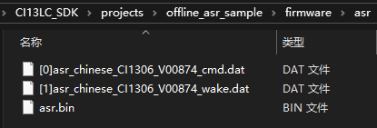
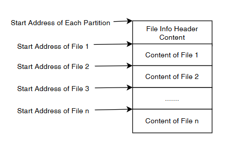
- File layout of
asr.binwithin firmware:
- File header field order:
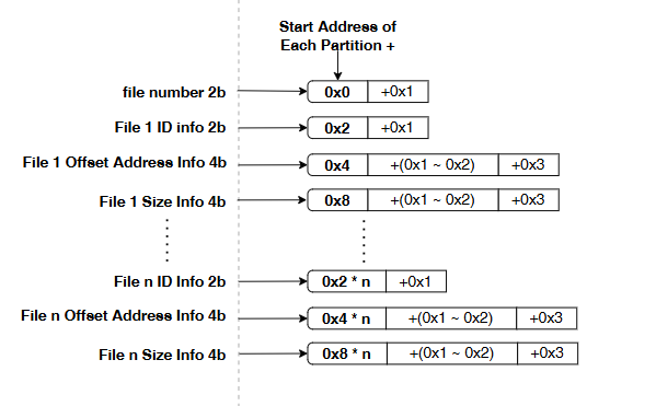
:
- Example: If ASR partition starts at 0x29000, the base contains the file header followed by file contents:
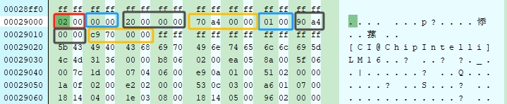
| File Header Field | Address | Value |
|---|---|---|
| file_number (count) | 0x29000 + 0x0 (red) | 0x01 (one file) |
| file_id (file1) | 0x29000 + 0x2 (blue#1) | 0x0 (ID 0) |
| file_addr (file1 offset) | 0x29000 + 0x4 (black#1) | 0x20 (offset 0x29000+0x20) |
| file_size (file1 size) | 0x29000 + 0x8 (yellow#1) | 0xA470 |
| file_id (file2) | 0x29000 + 0xC (blue#2) | 0x1 (ID 1) |
| file_addr (file2 offset) | 0x29000 + 0xE (black#2) | 0xA490 (offset 0x29000+0xA490) |
| file_size (file2 size) | 0x29000 + 0x12 (yellow#2) | 0x70C9 |
- The file header structures are defined as:
// In #include "ci_flash_data_info.h"

typedef struct
{
    uint16_t file_id;      // File ID
    uint32_t file_addr;    // File offset
    uint32_t file_size;    // File size

}file_header_t;

typedef struct
{
    uint16_t file_number;          // Number of files
    file_header_t file_header[1];  // Single file header entry
}file_table_t;           // Used as a variable-length array
7. DNN Partition File Layout
- The DNN bundle
dnn.bincan be composed of multiple files, e.g., file [0] combined into dnn.bin:
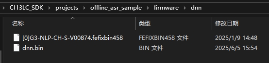
- DNN layout is identical to ASR; refer to the ASR example.
8. UserFile Partition File Layout
- The UserFile bundle
user_file.bincan be composed from multiple files, e.g., a spreadsheet “[60000]cmd_info.xlsx” converted (other bins are intermediate files):
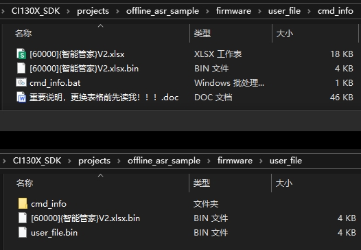
- UserFile layout is identical to ASR; refer to the ASR example.
9. Voice Partition File Layout
- The Voice bundle
voice.bincan be composed of multiple audio files, e.g., combining 10 files:
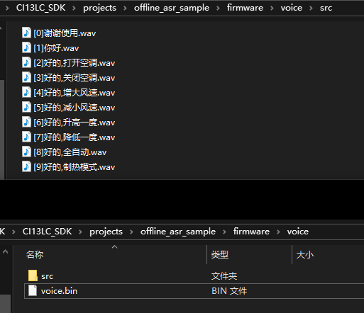
- Voice layout is identical to ASR; refer to the ASR example.
10. Example: Read Files from Partitions
- Example: Read the first file from the UserFile partition:
#include "flash_manage_outside_port.h"
#include "ci_flash_data_info.h"

#define COMMAND_INFO_FILE_TEST_ID    60000   // Target file ID in UserFile

partition_table_t partition_table = {0};     // Partition table struct

void read_user_file()
{
  // Assume partition table is already read (see section 5)

  read_partition_table();

  uint32_t user_file_addr = 0;
  uint32_t user_file_size = 0;

  uint32_t file_addr;
  // From UserFile partition base, get offset/size for ID 60000

  if (get_file_addr(partition_table.user_file_offset, COMMAND_INFO_FILE_TEST_ID, &file_addr, &user_file_size))
  {
    // Compute absolute Flash address for ID 60000

    user_file_addr = partition_table.user_file_offset + file_addr;
    uint8_t * userfile_buff = pvPortMalloc(user_file_addr);
    // Read content using absolute address and size

    post_read_flash((char *)userfile_buff,user_file_addr,user_file_size);
  }
}
- Alternatively, use helper APIs to get addresses/sizes and then read:
```c //位于#include “ci_flash_data_info.h”中
uint32_t get_userfile_addr(uint16_t file_id, uint32_t *p_file_addr, uint32_t *p_file_size) uint32_t get_dnn_addr_by_id(uint16_t dnn_file_id, uint32_t *p_dnn_addr, uint32_t *p_dnn_size) uint32_t get_asr_addr_by_id(int asr_id, uint32_t *p_asr_addr, uint32_t *p_asr_size) uint32_t get_voice_addr_by_id(uint16_t * voice_id_buffer, uint32_t * voice_addr_buffer, uint32_t voice_num)
// See SDK for Examples; these APIs are used together.