Inter-Integrated Circuit (I2C/IIC)
1. Introduction
- I2C is a bidirectional, two-wire, synchronous serial bus consisting of SDA (serial data) and SCL (serial clock). Both SDA and SCL pins are open-drain. I2C is commonly used for communication between one or more masters and one or more slaves. Each device on the bus has a unique address, and at any given time only one master may initiate a transaction to access a slave device.
- CI13XX supports one I2C controller. The data frame typically consists of Start, Address, Acknowledge, Data, and Stop. It supports Standard mode at 100 kbit/s and Fast mode at 400 kbit/s.
2. Features
- SDA: Serial Data line, bidirectional I/O.
- SCL: Serial Clock line, provided by the master.
- Supports master and slave modes configurable via API
iic_polling_init. - Master: Initiates bus transfers and generates the clock.
- Slave: Any addressed device with a unique address.
- Start condition: While SCL is high, SDA transitions from high to low to indicate the start of a transfer.
- Address: Supports 7-bit addressing, with 7-bit address and 1-bit R/W.
- Acknowledge: ACK indicates successful reception; NACK indicates failure or end of transfer.
- Data: Transferred by byte, MSB first, LSB last.
- Stop condition: While SCL is high, SDA transitions from low to high to indicate the end of a transfer.
- Bus speed configurable via
iic_polling_init: Standard (100 kbit/s) and Fast (400 kbit/s).
3. I2C Timing
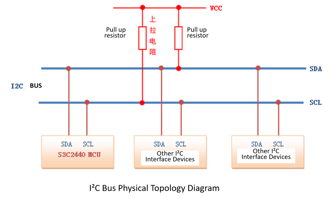
3.1 I2C Bus Physical Topology
- The I2C bus can connect multiple devices, typically one or more masters and one or more slaves. Each device has a unique address, and at any given time only one master may initiate an access to a slave device.
3.2 Timing Diagrams
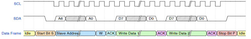
- (1) Continuous write timing:
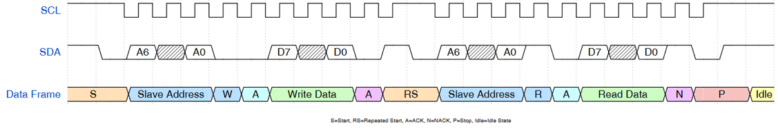
- (2) Write-then-read timing:
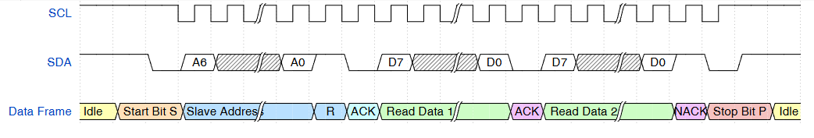
- (3) Continuous read timing:
- The master starts communication by generating a Start condition: pulling SDA low while SCL is high, then sending 8 SCL pulses to transfer one byte containing a 7-bit address and 1-bit R/W. If a slave address matches, it responds with ACK. Master and slave determine send/receive roles via the R/W bit and end the transfer based on ACK/NACK. During data transfer, SDA changes only when SCL is low. To end communication, the master issues a Stop condition by pulling SDA high while SCL is high.
4. API List
| Function Name | Description |
|---|---|
| iic_polling_init | Initialize in master or slave mode (polling) |
| iic_master_polling_send | Master polling send |
| iic_master_polling_recv | Master polling receive |
| iic_master_multi_transmission | Master multi-message transfer |
| iic_slave_polling_send | Slave polling send |
| iic_slave_polling_recv | Slave polling receive |
| iic_interrupt_init | Initialize in master or slave mode (interrupt) |
| iic_master_interrupt_send | Master interrupt send |
| iic_master_interrupt_recv | Master interrupt receive |
| iic_slave_interrupt_send | Slave interrupt send |
| iic_slave_interrupt_recv | Slave interrupt receive |
| i2c_master_only_send | Single message: send only |
| i2c_master_send_recv | Two messages: write then read |
| i2c_master_only_recv | Single message: read only |
5. Example
The following demonstrates I2C initialization and read/write:
#include "ci130x_iic.h"          /* Contains I2C interface definitions */
#include "ci130x_system.h"       /* Contains I2C registers and base addresses */


/* Without R/W bit: I2C device address << 1; with R/W bit becomes 0x40/0x41 */
#define IIC_TEST_SLAVE_ADDR  0x20


void i2c_master_test()
{
    /* Customizable I/O pin initialization */
    pad_config_for_i2c();


    /* Initialize master mode: bus IIC0, 100 kHz; own address 0 = master mode, valid value = slave mode; timeout */
    iic_polling_init(IIC0,100,0,LONG_TIME_OUT);


    /* Write 5 bytes to I2C device at address 0x20 */
    char send_buf[5] = {0x01,0x02,0x03,0x04,0x05} ;
    uint8_t last_ack_flag = 0;
    iic_master_polling_send(IIC0,IIC_TEST_SLAVE_ADDR,send_buf,5,&last_ack_flag);


    /* Read 5 bytes from I2C device at address 0x20 */
    char recv_buf [5] = {0} ;
    iic_master_polling_recv(IIC0,IIC_TEST_SLAVE_ADDR,recv_buf,5);

}
The following configures I2C pins (PB7/PC0) as open-drain outputs:
#include "ci130x_dpmu.h"


void iic_pad_init()
{
    dpmu_set_io_reuse(PB7,THIRD_FUNCTION);              // Set pin function to I2C
    dpmu_set_io_reuse(PC0,THIRD_FUNCTION);              // Set pin function to I2C
    dpmu_set_io_open_drain(PB7,ENABLE);                 // Enable open-drain, supports external 5V pull-up
    dpmu_set_io_open_drain(PC0,ENABLE);                 // Enable open-drain, supports external 5V pull-up
    dpmu_set_io_pull(PB7,DPMU_IO_PULL_DISABLE);         // Disable pull-up
    dpmu_set_io_pull(PC0,DPMU_IO_PULL_DISABLE);         // Disable pull-up
    dpmu_set_io_direction(PC0,DPMU_IO_DIRECTION_OUTPUT);// Configure SCL as output

}