CI-D02GS04U Module Datasheet
Module Introduction
Overview
This module is a universal, portable, low-power, high-performance voice recognition module developed for low-cost offline voice applications. Model: CI-D02GS04U, with CI1302 as the main chip (CI1301 and CI1303 can also be used as the main chip, but CI1301 does not support self-learning due to its smaller memory capacity). The CI1302 can recognize up to 300 offline wake words/commands and supports self-learning functions. This module enables offline voice infrared control of air conditioners, TVs, fans, lights, and other household appliances.
The module features:
- Compact size: 35mm × 26mm
- Operating voltage: 3.6V-5.5V with onboard power amplifier, built-in microphone and speaker, 5V power supply and UART USB interface, ready to use with USB power supply
- Main chip supports offline neural network computation, command word and wake word self-learning algorithms, single-microphone noise reduction enhancement, single-microphone echo cancellation, 360° omnidirectional sound pickup, effectively suppresses environmental noise, ensuring accurate voice recognition in noisy environments
- Offline voice recognition without network dependency, low latency, high performance, achieving over 97% recognition rate, 10-meter long-distance recognition, with response time as fast as 0.2 seconds
- High reliability with industrial-grade components, having passed multiple reliability tests
Main Chip Introduction
The CI1302 is an AI chip specifically designed for voice processing, widely applicable in household appliances, smart home devices, lighting, speakers, toys, wearables, automotive, and other product fields to achieve offline voice interaction and control. The CI1302 chip integrates a CPU core and Chipintelli’s self-developed Brain Neural Network Processor (BNPU V3), with a system frequency of up to 220MHz, built-in 640KByte SRAM, integrated PMU power management unit, high-precision RC oscillator, dual-channel high-performance low-power Audio Codec, and multiple peripheral control interfaces including UART, I2C, I2S, PWM, GPIO, and PDM. The chip requires only a few external components like resistors and capacitors to implement various intelligent voice product hardware solutions, offering excellent cost performance.
Module Application Scenarios
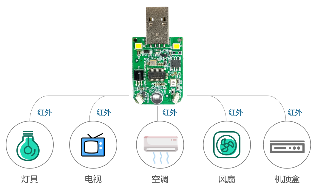
By default, this module supports matching and controlling devices with infrared remote control functions such as lights, TVs, air conditioners, fans, and set-top boxes. It also supports secondary development to add other infrared-controlled devices (e.g., wall-hung boilers, projectors, etc.).
This module can be directly used as an air conditioner companion remote control solution. The module comes with built-in microphone and speaker, and requires a suitable housing for application. It is powered by a 5V power supply through the USB interface.
Module Features
- Simplified Peripherals: Supports CI1301, CI1302, and CI1303 memory chips
- One-Button AC Matching: Supports voice control for TVs, set-top boxes, fans, lights, and other infrared-controlled devices
- Dialect Self-Learning: Solves recognition difficulties with regional dialects
- Universal AC Control: Compatible with 99% of air conditioners on the market
- Plug-and-Play: No network or Bluetooth connection required, works immediately after power-on
- Supports Secondary Development
Module Specifications
Physical Diagram
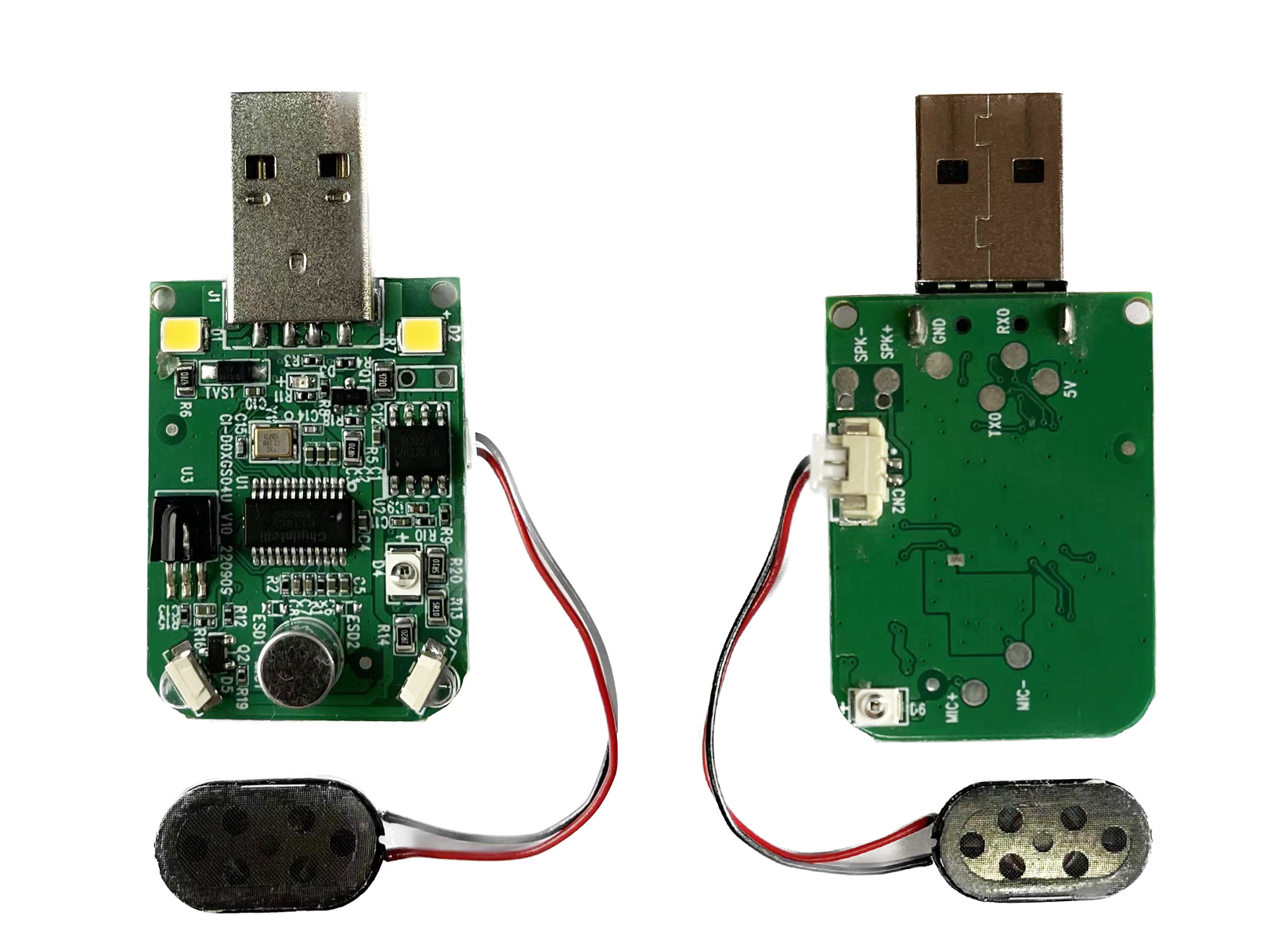
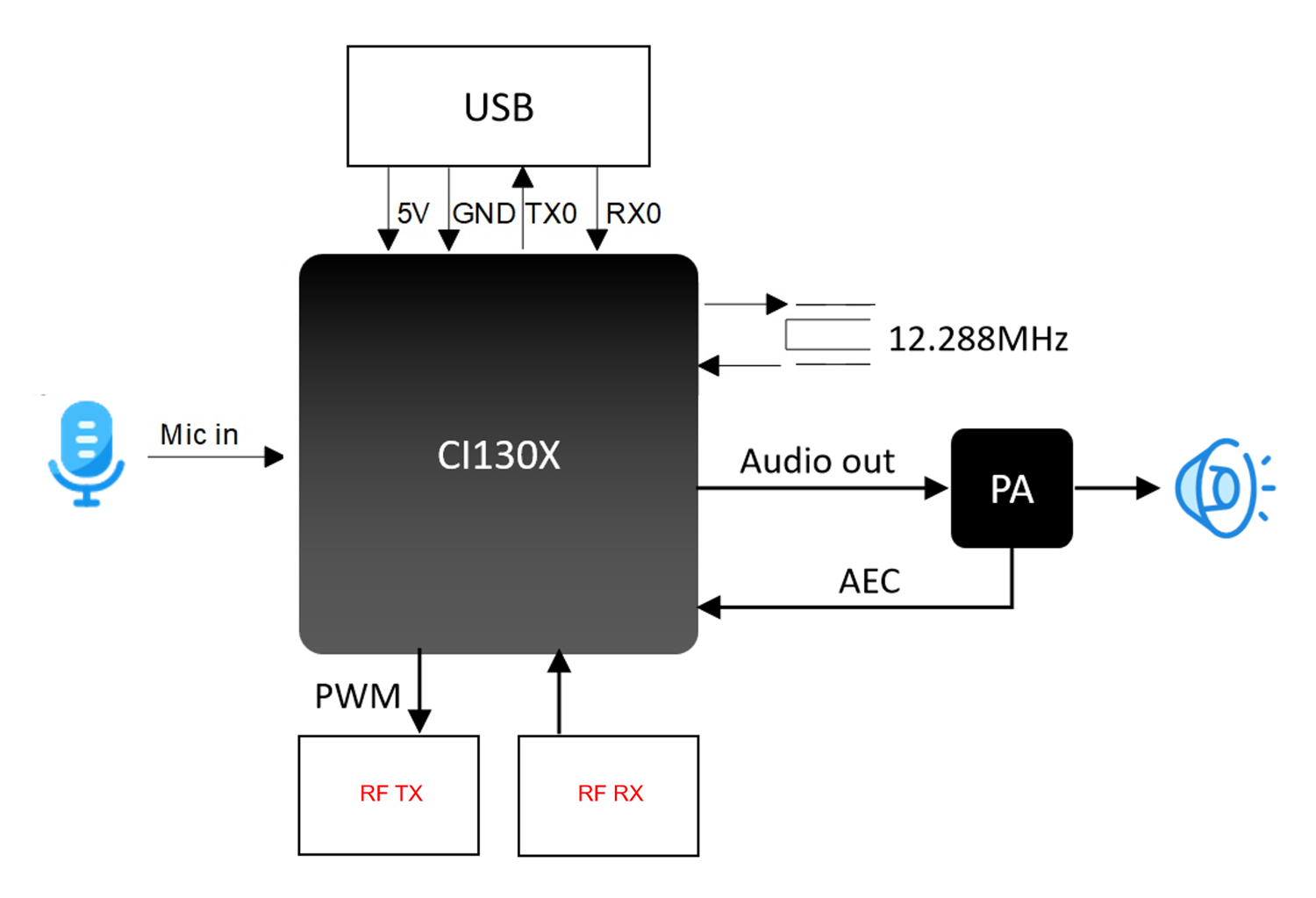
As shown in Figure 2, the voice recognition module features double-sided SMT assembly, with main ICs including the CI1302 voice recognition chip and power amplifier. Sound is input through a single microphone, processed by the voice IC, and then sent to the power amplifier to drive the speaker. The maximum output power of the amplifier is 1.5W@8Ω and 2W@4Ω.
Module Dimensions
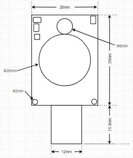
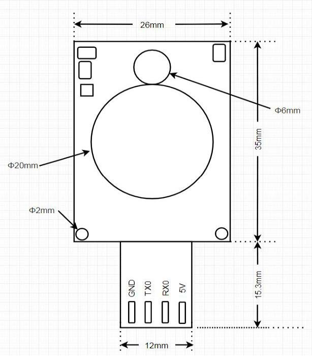
As shown in Figure 3, the module has a rectangular shape with the following specifications: - PCB dimensions: 35±0.15mm × 26±0.15mm - USB connector size: 15.3±0.1mm × 12±0.1mm - PCB thickness: 1.0±0.1mm - Module height: 10.8±0.4mm - Mounting hole diameter: 2mm - Distance from mounting hole center to board edge: 1.5mm - Speaker diameter: 20mm - Speaker height: 4.9mm - Microphone diameter: 6mm - Microphone height: 5mm
Users can design the housing structure based on these dimensions.
Hardware Interface Definition
The module includes the following functional interfaces:
-
USB Interface: Provides power supply, UART communication, and Firmware Update capabilities. Works with UART upgrade tools for quick and easy firmware updates.
-
Infrared Transmitters: Multiple IR transmitters are equipped to control appliances in all directions. The module also includes an IR receiver for receiving IR signals from remote controls.
-
Night Light: Features a built-in night light that provides soft, non-glaring illumination during nighttime use.
-
Self-Learning Function: Supports dialect and language learning to improve recognition accuracy for various regional accents.
Electrical Characteristics
The electrical parameters of the module are shown as follows:
| Parameter | Condition | Minimum Value | Typical Value | Maximum Value | Unit | Note |
|---|---|---|---|---|---|---|
| Module Supply Voltage | / | 3.6 | 5 | 5.5 | V | NOTE1 |
| Module Broadcast Current (Normal Volume) | 4 Ω 3W speaker | / | 70 | / | mA | NOTE2 |
| Module Working Current | / | / | 40 | / | mA | NOTE3 |
| Silent Environment Listening Current | 5V power supply | / | 35 | / | mA | / |
| Chip IO Interface Voltage | / | 3 | 3.3 | 5 | V | / |
| Module UART Interface Voltage | / | 3.3 | 3.3 | 5 | V | / |
NOTE 1: 5V is the typical operating voltage for the module. Input voltage exceeding 5.5V may damage the module.
NOTE 2: The module can reach a maximum instantaneous current of 760mA during IR transmission in audio playback mode. A power supply with at least 800mA driving capability is required.
NOTE 3: Typical value is measured in mute state. Maximum value is measured during recognition and audio playback.
Temperature and Humidity Parameters
The temperature and humidity parameters of D02GS04U are shown as follows:
| Parameter | Minimum Value | Typical Value | Maximum Value | Unit | Note |
|---|---|---|---|---|---|
| Module Working Environment Temperature | -40 | 25 | 85 | °C | / |
| Module Storage Environment Temperature | -40 | 25 | 100 | °C | / |
| Module Storage Humidity | 0% | / | 5% | RH | / |
Module Application
Power-up and Startup
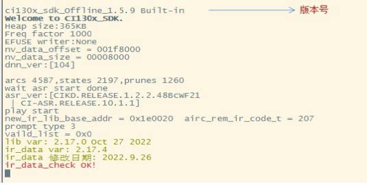
When using this module, plug in the USB to power it on. The module will start up, and the speaker will play a prompt tone. The UART port will output startup information, which can be viewed by connecting to a computer using a USB-to-UART converter. Set the baud rate to 921600. The module has successfully started when you can see the printed information in the serial debugging software, as shown in Figure 5.
The input 5V power supply is stepped down to 3.3V and 1.2V through the internal LDO for the main chip. The power amplifier on the module uses the 5V power supply directly. The 5V power supply must provide a rated current of 1A with stable output and ripple below 300mV.
Default Command Words
For mass production modules, customer-specified command word firmware is typically pre-loaded before shipment. If no custom commands are specified, the module comes with default firmware containing preset command words for testing purposes, as shown in Figure 6.

Self-Learning Function
To address compatibility issues with regional accents or dialects that may limit usage in certain areas, this module includes a self-learning feature.
Study Wake Words
- In a quiet environment, say the command “Study wake word”
- Wait for the prompt tone, then clearly speak your desired wake word (e.g., “Xiaomei Xiaomei”)
- Wait for the success confirmation tone
- The wake word is now active (e.g., use “Xiaomei Xiaomei” to wake the device)
To delete a learned wake word: 1. Say “I want to delete” 2. After the prompt tone, say “Delete wake word”
Note: Always perform learning in a quiet environment. Background noise during learning may result in poor recognition.
Study Command Words
The module can learn commands for the following functions by default: turn on/off air conditioner, turn on/off TV, turn on/off fan, turn on/off lights.
- Say “Study command word”
- Follow the voice prompts to learn new commands
- After learning, you can use the newly learned commands to control devices
- To exit learning mode, say “Exit learning”
- To delete learned commands, say “I want to delete” and after the prompt tone, say “Delete command word”
Default Serial Communication Protocol
The module’s default firmware supports a serial communication protocol for communication with the MCU. This serial protocol is extensible and features:
-
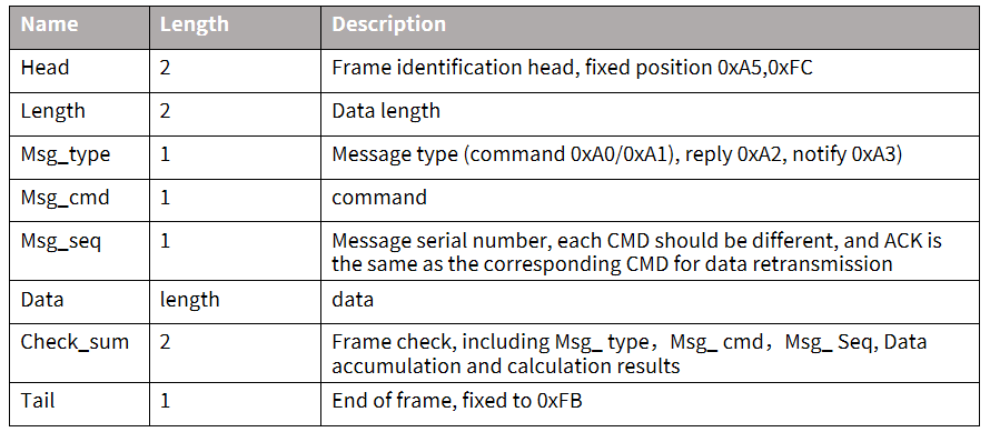
Complete transmission packets including: header/footer, length, checksum, message type, and message sequence number. Supports variable-length commands for easy expansion.
-
Message types (command, notification, response).
-
Command messages are configurable with ACK responses. Notification messages do not require ACK.
-
The message format is the same as that used for bootloader upgrades, differentiated by header from the bootloader protocol. Default baud rate is 9600 bps.
Note: The module only reserves the UART0 interface, which defaults to print output. To use UART0 for the serial protocol interface, code modifications are required. Refer to the CI130X serial protocol documentation for implementation details.
- Supported commands: Query protocol version, query system version, set volume (volume levels defined in user_config.h), play local audio prompts, reset command, etc. The protocol format is shown in the figure below:
Example 1:
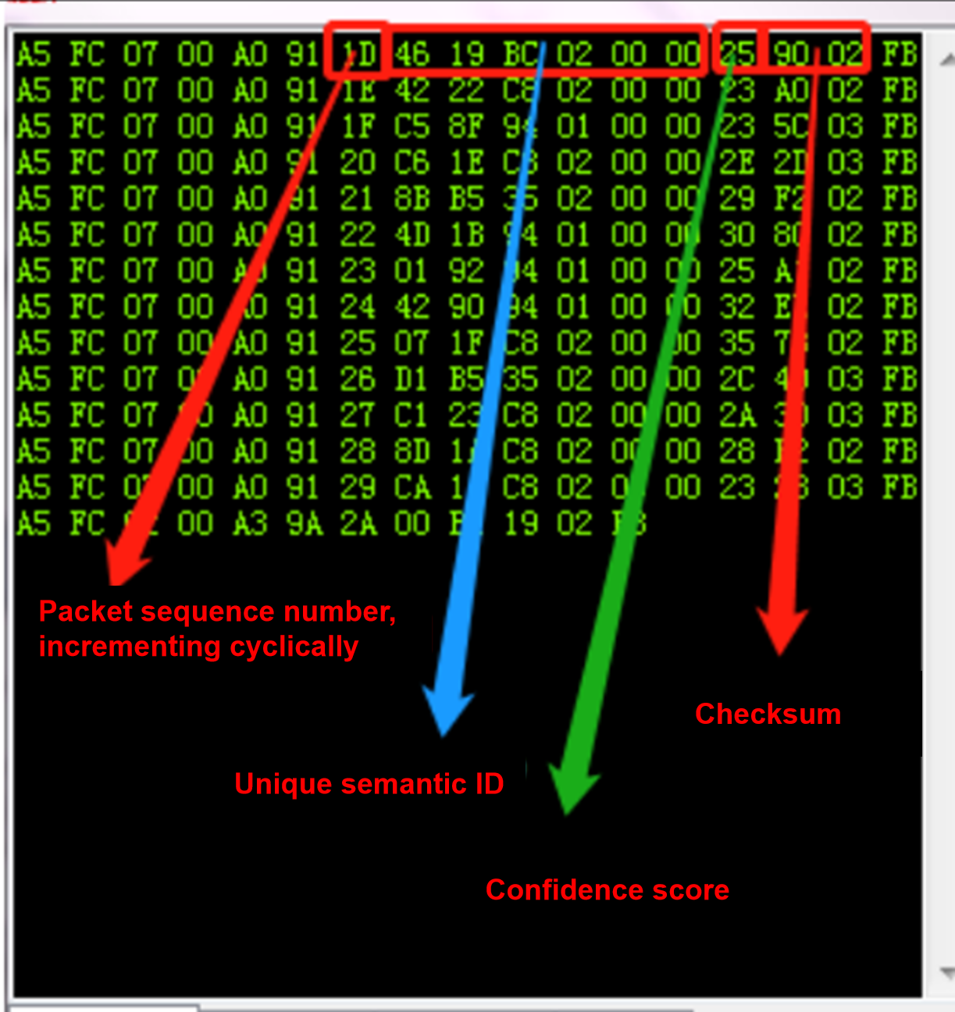
A5 FC 07 00 A0 91 18 01 55 E0 01 00 00 1B 9B 02 FB is parsed as follows:
- A5 FC: Header
- 07 00: Valid data length is 7 bytes
- A0: Command word information
- 91: Command number 0x91 (this data content is command word data)
- 18: Packet sequence number, 0x08th data transmission from this serial port (this value increments continuously)
- 01 55 E0 01 00 00: Command word data, total 6 bytes
- 1B: Checksum
- 9B 02: Command word ID in little-endian format (high byte last, low byte first), 0x029B = 667
- FB: XOR checksum
Example 2:
A5 FC 02 00 A3 9A 17 00 B1 05 02 FB is parsed as follows:
- A5 FC: Header
- 02 00: Valid data length is 2 bytes
- A3: Notification data
- 9A: Command number 0x9A (this data content is notification data)
- 17: Packet sequence number, 0x07th data transmission from this serial port (this value increments continuously)
- 00 B1: Notification data, total 2 bytes
- 05 02: Checksum
- FB: XOR checksum
Note: If the application only needs to focus on command words and thresholds, it can only focus on the blue part of the 7 valid data bytes.
The following is a reference screenshot of the protocol data:
Software Development
The module comes with default firmware for initial user experience. For software development, users need to register and log in to the Chipintelli AI Platform, and perform rapid development of voice firmware. The SDK and related hardware materials can be downloaded from the “Development Materials” section of the Chipintelli AI Platform.
New users can refer to the “New User Guide” to understand the development process, and also refer to the video tutorials in the documentation center to learn more about the development process and SDK development.
The software development process mainly includes the following steps:
- Downloading the SDK development package
- Creating models (language model + acoustic model)
- Voice synthesis
- Associating command word information with audio files
- Firmware packaging
For detailed development process, please refer to the CI130X Chip SDK documentation.
A5 FC :head
02 00:valid data 2byte A3 :current notification data
9A :command number 0X9A(this data content is voice module content change)
17:This serial port has been transmitted 0x07 times, this value is continuously incremented
0 B1:valid data.(This data indicates that the module has entered the wake-up state)
5 02:cumulative sum
FB:ending data
Note: This data is notification data, and users can choose to use this information based on their needs.
Below is a reference screenshot of the protocol data:
Software Development
The default firmware comes with the module for initial user experience. If users want to develop software, they need to register and log in to the Chipintelli AI Platform, and perform rapid development of voice firmware. The SDK and related hardware materials can be downloaded from the “Development Materials” section of the Chipintelli AI Platform.
New users can refer to the “New User Guide” to understand the development process, and also refer to the video tutorials in the documentation center to learn more about the development process and SDK development.
The software development process mainly includes the following steps:
- SDK development package download
- Model generation(language model + acoustic model)
- Voice synthesis
- Association of command word information with audio files
- Firmware packaging
For detailed development process, please refer to the CI130X Chip SDK documentation.
Firmware Flashing
Flashing Preparation
Before flashing the module, users need to prepare the following items:
-
Module to be flashed
-
USB to serial port adapter, using 4 Dupont wires to connect to the USB母头. The firmware flashing tool (pack_update_tool.exe) is included in the SDK.
-
Firmware information (*.bin format file)
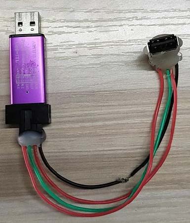
Hardware Connection and Flashing
As shown in the above figure, the module USB is inserted into the USB母头 to achieve flashing. Open the firmware flashing tool (the tool can be found in the SDK development package CI130x_sdk\tools directory PACK_UPDATE_TOOL.exe), select the corresponding model according to the chip, click the Firmware Update button, select the made firmware file, and find the corresponding computer port number allocated to the USB to serial debug tool. After the preparation is ready, insert the dongle board into the USB to start flashing. If the USB to serial debug tool cannot be recognized on the computer, please install the corresponding driver on the computer. When the display shows 100%success, the download is complete. After downloading, the board needs to be powered off and then powered on to start normally.
Function Test
After firmware flashing is successful, it is recommended to test the module function to verify whether the flashing firmware is successful. Test whether the wake-up word and command word can be normally awakened and recognized. If both can work normally, then the module function is normal, and the flashing is successful; otherwise, the flashing fails, and further investigation is needed.
Other Application Notes
It is recommended that users wear anti-static wrist straps, gloves, or finger cots during inspection and soldering production to ensure product quality and reliability.
Note that the default UART of this module operates at 3.3V. Please use a 3.3V level UART for communication. If 5V power supply is required, code modification is necessary. Users can use a USB-to-UART converter for software debugging. During debugging, add UART print commands at the appropriate locations in the SDK software, then compile to generate the firmware and flash it for verification.
Production Guide, Storage, and Packaging Information
Production and Storage Guidelines
Chipintelli’s stamp-hole packaged modules must be mounted using SMT equipment (except for pin header mounting). Once the package is opened, SMT mounting must be completed within 24 hours; otherwise, the module must be re-vacuum packaged.
Storage conditions for Chipintelli’s stamp-hole packaged modules are as follows: Vacuum moisture barrier bags must be stored in a constant temperature and humidity warehouse at 25±5°C and 65%±10% RH.
Other Application Notes
Since the CI1302 & CI1303 chips have a high ESD rating and the module is designed for user expansion, no ESD protection devices are included in the module design. For products with high ESD requirements, ESD protection devices can be added to the baseboard at the microphone, speaker, and power socket locations. It is recommended that users wear anti-static wrist straps, gloves, or finger cots during inspection and soldering production to ensure product quality and reliability. Pay attention to correctly connect the microphone, speaker, and power UART ports.
Users can use a USB-to-UART converter for software debugging. During debugging, add UART print commands at the appropriate locations in the SDK software, then compile to generate the firmware and flash it for verification.
All I/Os on this module board operate at a typical 3.3V level and are also 5V tolerant.
When designing the module’s baseboard or host motherboard, place a capacitor with a capacitance of no less than 100μF at the 5V power input of the module. Keep microphone traces as short as possible and ensure they are properly shielded. Speaker (SPK) traces should be kept short and wide, with no other traces crossing over them. The warpage of the control baseboard should not exceed 0.5% to prevent poor module soldering.
Purchasing and Technical Support
To purchase samples of our products, please click ☞Sample Purchase, or visit ☞Samples and Bulk Purchasing for more information.
For technical support, please log in to ☞Chipintelli AI Platform.