Click to Download PDF Document
Production Testing
This document describes the methods for mass production firmware flashing and functional testing of modules developed using our company’s chips.
Overview
Our company has developed dedicated automated flashing and testing fixtures (hereinafter referred to as “fixtures”) for firmware flashing and functional testing during mass production. We have developed corresponding fixtures for different standard modules, and users can also develop their own fixtures according to the methods described in this document. These fixtures can complete flashing and testing in one automated process, improving production efficiency while ensuring all functions of the voice modules work properly after mass production, including module electrical functions, voice recognition, and voice broadcast.
The core of the fixture is our self-developed test motherboard, which enables automatic flashing and testing functions. For different modules under test, different test firmware can be designed and pre-flashed into the test motherboard. Once the test motherboard is installed, one-click flashing and testing can be achieved. A single test motherboard can support 1-to-4 flashing and testing, and a single fixture can accommodate multiple test motherboards (assuming N test motherboards are installed). Each test motherboard works independently, enabling N × 4 modules to be flashed and tested simultaneously.
The following uses a 1-to-4 fixture developed by our company as an example to explain how to use the fixture.
1 Testing Fixture Introduction
1.1 Testing Fixture Set
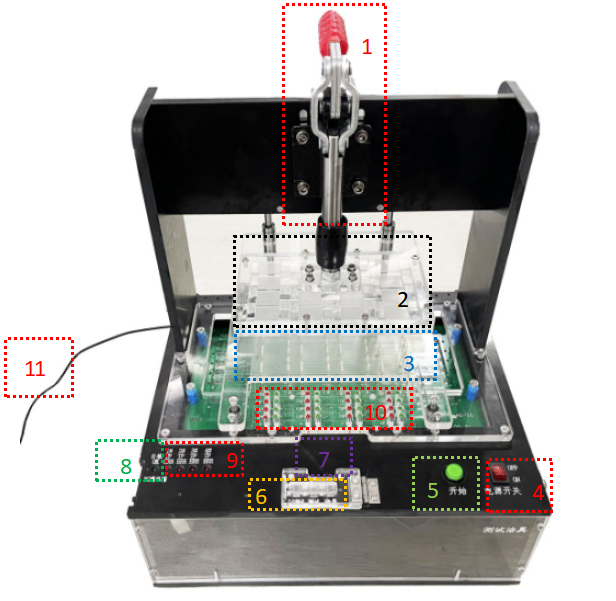
| No. | Name | Description |
|---|---|---|
| 1 | Pressure Bar | Provides downward mechanical force with the pressure plate |
| 2 | Pressure Plate | Provides downward mechanical force with the pressure bar |
| 3 | Carrier Board | Secures the module under test |
| 4 | Power Switch | Controls the fixture’s power on/off |
| 5 | Start Button | Initiates flashing or testing |
| 6 | Mode Selector | Selects test mode (flash, Test, I/O Test) |
| 7 | Mode Indicator | Lights up when the corresponding mode is selected |
| 8 | Self-test Green LED (1) | Blinks during self-test, stays on when complete |
| 9 | Self-test Red LEDs (4) | Stays on if self-test fails, leftmost is Red LED #1 |
| 10 | Module Indicators | One set of red/green lights per module, numbered accordingly |
| 11 | Power Cable | Connects to the power adapter |
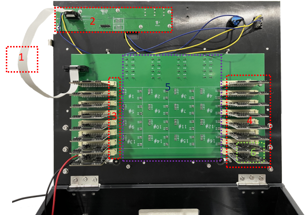
| No. | Name | Description |
|---|---|---|
| 1 | 10-pin Cable | Connects control board to adapter board |
| 2 | Control Board | For manual operation and status display |
| 3 | Test Motherboard Slot | For installing test motherboards |
| 4 | Test Motherboard | For testing the corresponding modules |
| 5 | Adapter Board | For installing probes and mounting test motherboards |
| 6 | TF Card Slot | For securing the TF card |
1.2 Module and Status LED Matching Instructions
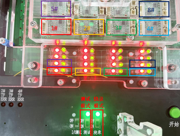
As shown in the figure below, the position numbers of the modules under test correspond to the positions on the adapter board. Both the indicators and the modules under test are numbered in order from left to right and bottom to top, with the bottom-left module being #1 and its corresponding indicator also being the bottom-left #1. (In Figure 1-3, status LED of the same color correspond to modules of the same color).
Flashing mode and testing mode are selected via the DIP switch. When a mode is selected and activated, the corresponding status LED lights up.
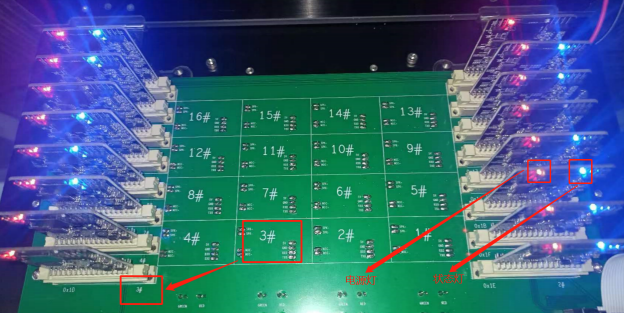
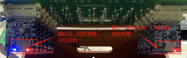
On the back of the adapter board, there are position numbers for the modules under test and corresponding test motherboard numbers. Each test motherboard has an onboard red power LED (stays on when powered) and a blue status LED (blinks during normal operation), as shown in Figure 1-4 below:
2 Testing Fixture Flashing and Testing Process
2.1 Operation Video
For specific operation procedures, please click Chipintelli Testing Fixture Operation Steps to watch the video.
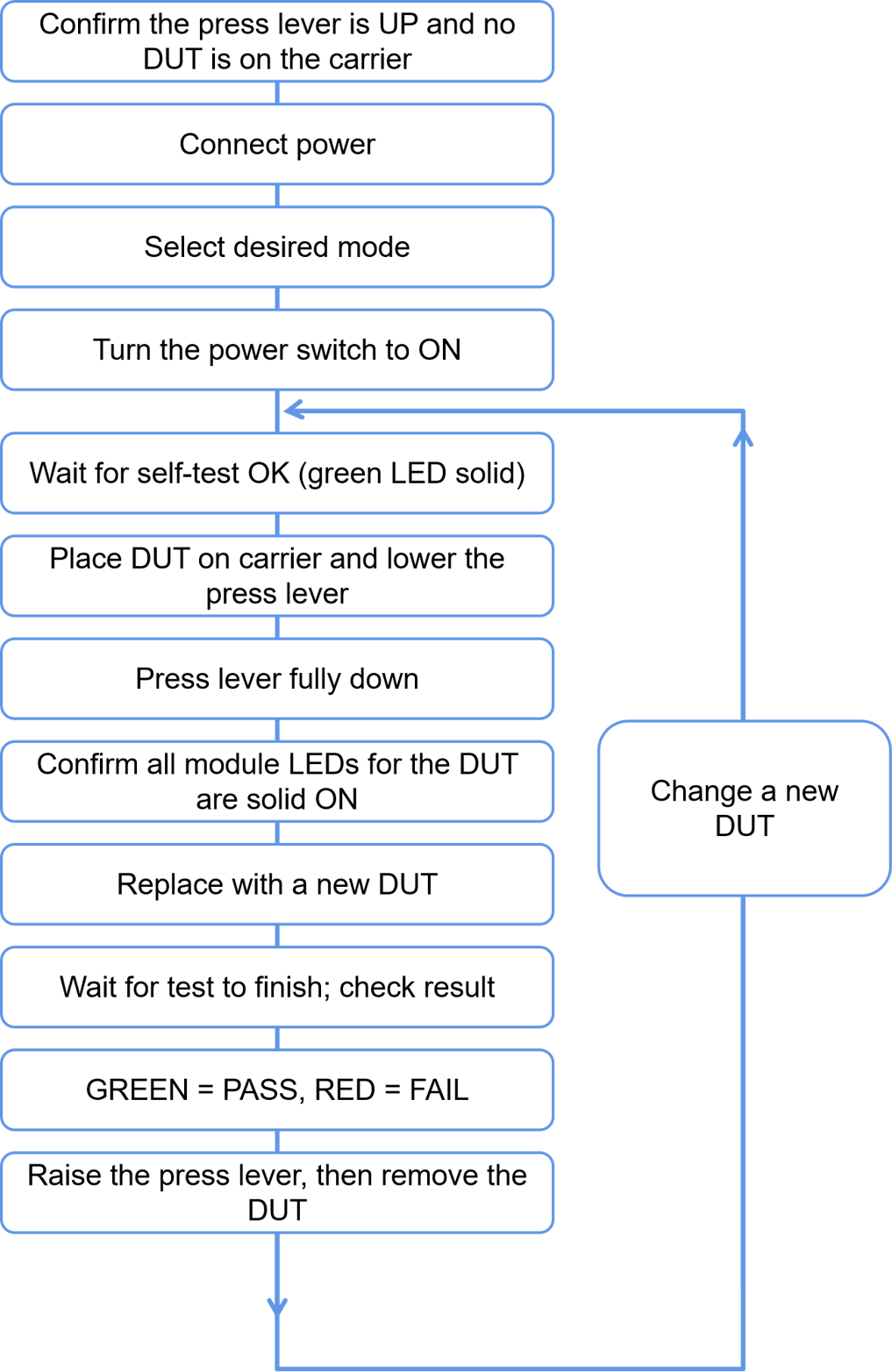
2.2 Operation Flowchart
2.3 Operation Precautions
- When updating TF card contents, please turn off the power before inserting or removing the card;
- First-module inspection is mandatory to confirm normal functionality; Chipintelli’s flashers can be used for verification. Refer to the Chipintelli flasher Manual for verification methods;
- Self-test precautions: Wait until the self-test green LED stays on before performing other operations;
- When using a computer to modify TF card contents, ensure the computer is virus-free before inserting the TF card. Hot-plugging is strictly prohibited;
- Ensure the test motherboard and TF card are properly inserted. Check for loose connections as poor contact will cause self-test failure and the control board’s red LED will stay on;
- Use only the dedicated power adapter provided by Chipintelli;
- All TF cards in the fixture must have identical contents, otherwise self-test will fail and the control board’s red LED will stay on.
3 TF Configuration
3.1 TF Configuration Tool
The TF Card Configuration Tool is used to configure the TF card configuration files for the production testing fixture. It generates corresponding configuration files by manually selecting the required test functions. This TF Card Configuration Tool is based on Production Fixture V2.4.2 and is not compatible with other versions.
3.1.1 TF Tool Interface
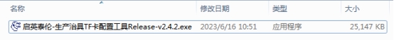
The TF Card Configuration Tool interface is shown in Figure 3-1 below. Double-click to run the “Chipintelli-Production Fixture TF Card Configuration Tool Release-v2.4.2.exe” file.
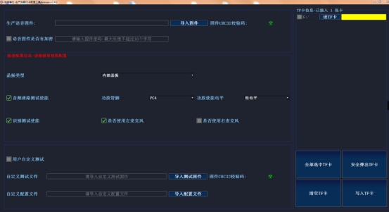
The running interface details are shown in Figure 3-2:
3.1.2 TF Operation Instructions
This section explains how to use the TF Card Configuration Tool.
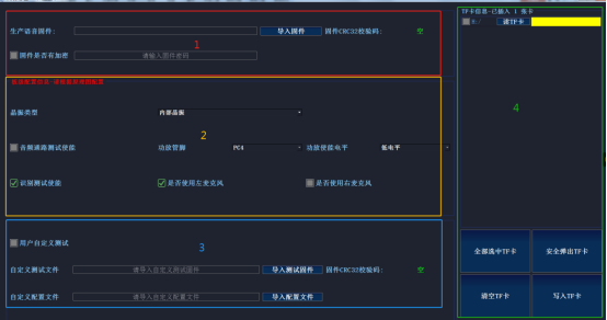
Detailed interface descriptions are provided in Table 3-1:
| No. | Functional Area Name | Description |
|---|---|---|
| 1 | Production Voice Firmware Configuration | 1. Import production voice firmware and verify checksum 2. For encrypted firmware, check “Is Firmware Encrypted” and enter password |
| 2 | Module Under Test Parameter Configuration | 1. Select crystal oscillator presence based on schematic 2. Audio path testing (requires correct configuration of amplifier pin and enable level) 3. Recognition testing 4. Configure microphone parameters per schematic |
| 3 | Custom Function Test Configuration | 1. Import custom test firmware and config files as needed 2. No configuration needed for standard test solutions 3. Additional test requirements may need custom firmware |
| 4 | TF Card Management | 1. TF card selection 2. Eject TF card 3. Read TF card 4. Clear TF card 5. Write to TF card |
The interface is shown in Figure 3-3:
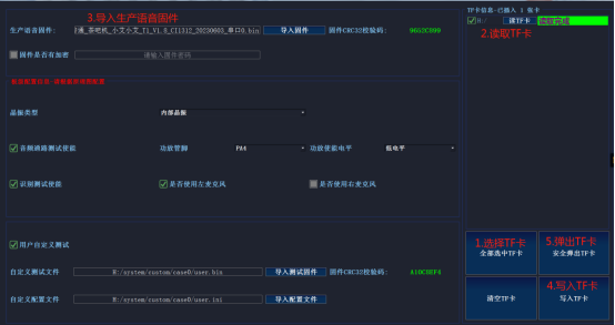
There are two scenarios for configuring the TF card:
Scenario 1: Only the production voice firmware is modified, hardware parameters remain unchanged.
Operation steps:
1. Select the TF card to be modified;
2. Read the TF card to load current configuration parameters into the interface;
3. Select the new production voice firmware and verify the CRC32 checksum matches the work order;
4. After configuration, write to TF card and confirm successful writing;
5. Safely eject the TF card.
As shown in Figure 3-4:
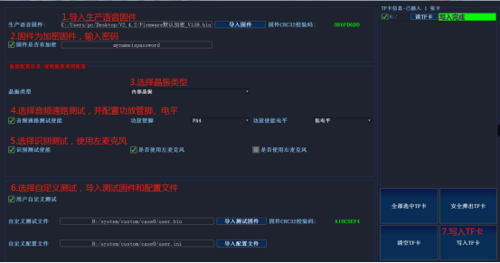
Scenario 2: Completely new TF card configuration, using an encrypted CI1312 firmware as an example.
Operation steps:
1. Select the TF card to be configured (current TF card is empty) and import the encrypted production voice firmware “Firmware_Default_Encrypted_V159.bin”;
2. Check “Is Firmware Encrypted” and enter the corresponding password (must match the SDK settings);
3. Based on the module’s schematic, select internal crystal oscillator, enable audio path testing, and configure amplifier pin as PA4 with active-low enable;
4. Enable recognition testing;
5. Optionally enable custom testing and configure custom test firmware and configuration files (if not needed, leave this unchecked);
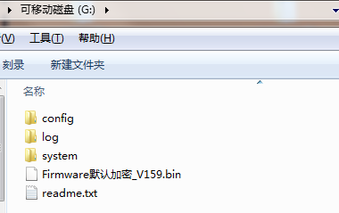
6. Write configuration parameters to the TF card and confirm successful writing (interface shown in Figure 3-5, TF card contents after writing shown in Figure 3-6);
7. Safely eject the TF card.
3.1.3 TF Operation Notes
-
When using, the imported production voice firmware must be configured according to the design schematic of the module under test;
-
After configuration is complete, take a screenshot and store it with the voice firmware;
-
After writing to the TF card, safely eject the TF card before removing it;
-
Writing other data to the production TF card is prohibited.
3.2 TF Card Content Description
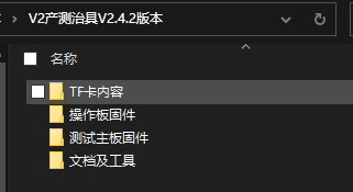
3.2.1 Software Package
After decompressing the “V2 Production Fixture V2.4.2” package we provide, the contents include control board firmware, test motherboard firmware, TF card contents, documents, and tools. The subfolders under TF card contents need to be configured according to different solutions before being copied to the TF card.
(1) sdcard_ci130x_inner_rc folder: Applicable to CI1301, CI1302, CI1303, CI1306, CI1311, and CI1312 chip solutions, where the tested board does not have an external crystal oscillator and uses the internal chip oscillator;
(2) sdcard_ci130x_outside_osc folder: Applicable to voice chips CI1301, CI1302, CI1303, CI1306, CI1311, and CI1312, where the tested board has an external crystal oscillator.
3.2.3 TF Card Content
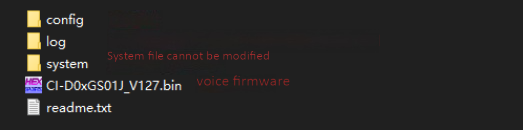
Note: Even if the flashing function is not needed, the production voice firmware for the module under test must not be deleted.
4 Testing Fixture Troubleshooting
4.1 Control Board Self-test Failure (Red Light On)
- Control board self-test red light status description
| Status | Description |
|---|---|
| Red Light 1 Stays On | Inconsistent TF card configuration content, specifically the firmware to be flashed for the module under test is inconsistent. Please check the TF card contents on each test motherboard. |
| Red Light 2 Stays On | Test motherboard failed to read TF card. See point 2 below for details. |
| Red Light 3 Stays On | Incorrect TF card configuration. Confirm the corresponding test motherboard position. See point 2 below for details. |
| Red Light 4 or Green Light Blinking | Test motherboard is performing self-update. Colors may vary between different fixtures. |
- Open the fixture frame and check the status of the onboard indicators on each test motherboard:
| Test Motherboard Onboard Indicator Status | Description and Corrective Actions |
|---|---|
| Blue Light Blinking, Red Light On | Self-test successful |
| Blue Light On, Red Light On | Self-test failed 1. Some test motherboards failed self-test. Confirm the TF card is inserted stably without looseness. Power off and try another TF card from a board that passed self-test. If self-test passes, check if the TF card or its contents are normal. 2. If all test motherboards fail self-test. There may be an issue with the TF card contents. If changes were made, first copy back the original TF card contents. After successful self-test, make the relevant configuration changes while checking the log file in the highest-numbered TF card for specific reasons. |
| Blue Light Off, Red Light On | Reflash the test motherboard firmware and check TF card configuration. If there are log files in the TF card, check the log with the highest number for specific reasons. |
4.2 Abnormal Indicators on Adapter Board
| Status | Description |
|---|---|
| Red light blinks when pressing the pressure bar, green light stays off | Excessive current when loading the corresponding test board. Replace the board and test again. |
| Both red and green lights stay off when pressing the pressure bar | Insufficient current when loading the corresponding test board. Re-press the board. If still not working, replace the board and test again. If still not working, check if the fixture hardware has good contact. |
| Red light stays on and green light stays off after starting the test | The corresponding test board failed flashing or testing. |
| Red and green lights blink alternately and then stay on together | System crash. Please power cycle the production testing fixture. |
| Red light stays on and green light stays off when replacing the board in the fixture | 1. Previous test failed, and the current test board has insufficient loading current. Re-press the board. If still not working, replace the board and test again. If still not working, check if the fixture hardware has good contact. 2. System crash. Please power cycle the production testing fixture. |
4.3 High Defect Rate or Unstable Testing
If there are many defective test boards, or the same test board sometimes passes and sometimes fails testing, please note:
-
Check the needle marks on the test points of the module under test to ensure the pogo pins on the adapter board are making contact with the center of the test points. If there are no issues, check if the pogo pin spring specifications meet the test requirements;
-
Check if there is any oxidation on the test points of the module under test.
4.4 Failure in TF Card Log Files
| No. | Phenomenon | Possible Causes | Solution |
|---|---|---|---|
| 1 | After the module under test completes flashing or testing, the green light on the adapter board does not turn off when unloading the module | System crash | Restart the production testing fixture and re-flash or test the previous module. |
| 2 | The red power light on the test motherboard does not light up | Test motherboard power supply System exception |
1. Check if the test motherboard is properly inserted without looseness. 2. Replace the test motherboard. |
| 3 | Flashing failure | 1. Incorrect TF card configuration 2. Poor contact at 5V, GND, RX0, TX0, (PG_EN) test points 3. Functional defect in the module under test |
1. Check the log file in the TF card to modify the relevant TF card configuration 2. Ensure good contact at 5V, GND, RX0, TX0, (PG_EN) test points 3. Check the cause of the module defect, repair, and then flash again. |
| 4 | Electrical test failure | 1. Check for module functional defects 2. Check if the electrical parameter settings in the config file in the TF card are unreasonable |
1. Check the cause of the module defect, repair, and then test again 2. Modify the TF card electrical test configuration based on the log file in the TF card |
| 5 | Recognition test failure | 1. Test program download failure 2. Poor contact at test points 3. Module functional defect |
1. Confirm if RX0, TX0, and PGEN have good contact; check if the module waveform deviation changes too much 2. Confirm good contact at mic and spk test points |
| 6 | Frequency sweep test failure | 1. Test program download failure 2. Poor contact at test points 3. Module functional defect |
1. Confirm if RX0, TX0, and PGEN have good contact; check if the module waveform deviation changes too much 2. Confirm good contact at mic and spk test points |
Important Notice
-
This document is the property of Chipintelli. No part of this document may be reproduced, modified, adapted, published, translated, or disclosed to any third party without the prior written permission of Chipintelli.
-
The third-party software mentioned in this document is copyrighted by its respective authors. Users should contact the software authors directly for permission to use the software. Chipintelli shall not be liable for any loss or damage arising from the illegal use of this software.
-
Product improvement is an ongoing process. We are committed to providing our customers with superior products!