CI1332X Series - Call Noise Reduction Solution
1. Solution Introduction
1.1 Solution Overview
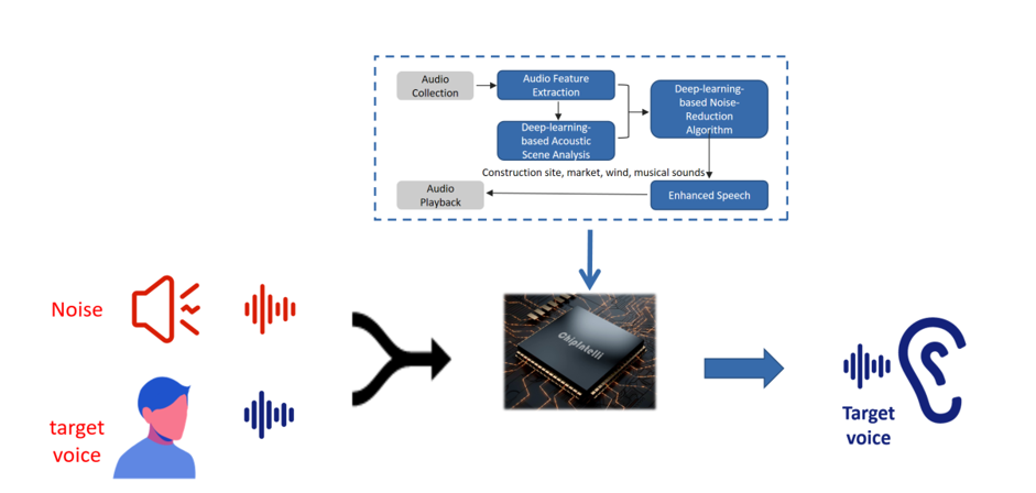
With the continuous improvement of living standards, there is an increasing demand for higher product quality and user experience. Coupled with intensifying competition across industries and the advent of the AI era, various fields are embracing intelligent features to enhance product value and market appeal. Chipintelli leverages the efficient AI computing capabilities of BNPU to provide noise reduction solutions for call products, significantly improving call audio quality.
1.2 Hardware Solution
This chip is designed for voice noise reduction applications, featuring a universal, portable, low-power, and high-performance AI ENC noise reduction solution. The chip model is: CI13322. It is widely applicable in various voice noise reduction scenarios such as intercoms, microphones, and headsets.
Supported noise types include: wind noise, howling, keyboard sounds, traffic noise, music, and crowd noise.
EQ adjustment is supported.
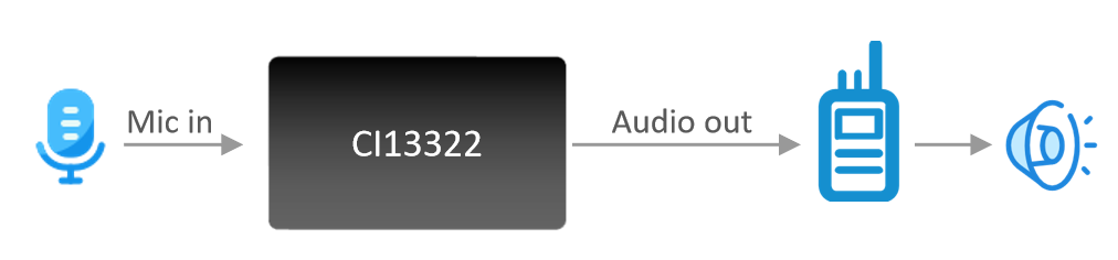
1.3 Functional Diagram
The functional block diagram of this solution is as follows:
1.4 Noise Reduction Parameters
| Parameter | Description | Min | Typical | Max | Unit | Remarks |
|---|---|---|---|---|---|---|
| SNR | Ratio of voice to background noise | ≥-5 | ≥0 | - | dB | - |
| Noise Suppression | Maximum introduced noise | - | - | ≤80 | dB | - |
| Power-on Time | Time from power-on to noise-reduced audio output | - | <200 | - | ms | - |
| Processing Delay | Time from audio input to noise-reduced output | - | 78 | - | ms | - |
| Pickup Distance | Distance from voice to microphone | - | ≤10 | - | cm | Contact our sales or FAE for custom parameters |
| Microphone | Recommended omnidirectional mic sensitivity | -58 | - | -32 | dB | Contact our sales or FAE for custom parameters |
| Input Level | Input amplitude when directly connected to audio signal | - | 0.5 | 0.7 | V | Contact our sales or FAE for custom parameters |
1.5 SNR Improvement Capability
SNR (Signal-to-Noise Ratio) improvement data in various environments, with an average improvement of approximately 40dB.
SNR Improvement Data Table
| Test Environment | Original Audio SNR (dB) | Noise-Reduced Audio SNR (dB) |
|---|---|---|
| White Noise | 10.85 | 43.95 |
| Marketplace | 4.30 | 47.34 |
| Supermarket | 5.39 | 47.04 |
| Wind Noise | 4.13 | 49.88 |
| Construction Site | 7.46 | 39.25 |
| Intersection | 7.37 | 52.11 |
| Barber Shop | 5.77 | 49.39 |
| Bubble Tea Shop | 6.39 | 49.46 |
| Shopping Mall | 3.55 | 42.08 |
| Arcade | 6.30 | 48.65 |
| Average | 6.15 | 46.92 |
1.6 Additional Features
In addition to call noise reduction, the CI13322 also supports recording, VOX, and audio broadcasting functions.
By default, it supports analog audio input and outputs noise-reduced analog audio. It also supports UART and I2S audio transmission. For custom requirements, please contact our business team through the official website. Chipintelli Business Contact
2. Development and Testing Preparation
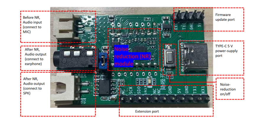
2.1 Development Board Description
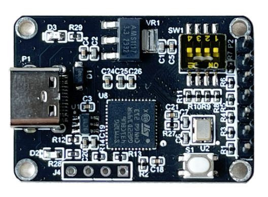
Developers can use the CI-F32XGS01S+CI-F32XGS01S_MB module board with CI13322 as the main chip. It can be purchased from our online store or by contacting our customer service.
Module Board Physical Connection Diagram:
Module Board Block Diagram:
This module board supports single microphone input, with noise-reduced analog audio output through the DAC port to the power amplifier, which then plays the audio through the speaker. It also supports listening to the noise-reduced audio through headphones. The board operates on 5V power supply and supports an 8Ω 2W speaker.
2.2 Development Board Testing
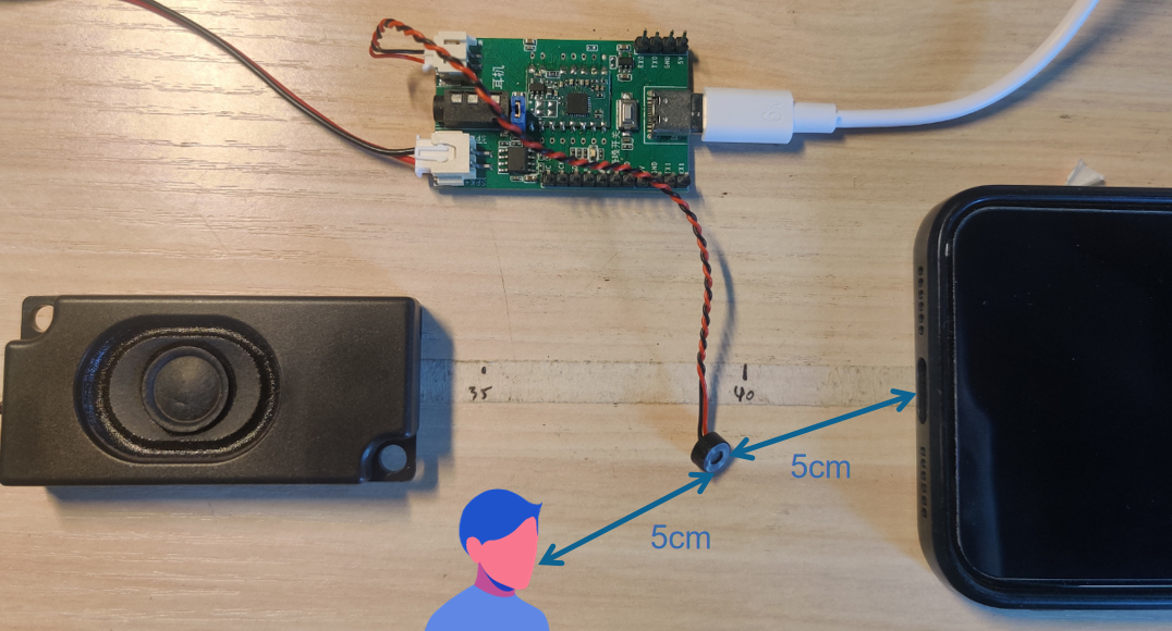
Testing Connection Diagram:
-
Connect the 5V power supply (Type-C interface) and attach a speaker or headphones. Place the speaker close to your ear. For optimal noise reduction demonstration, position the noise source 5cm from the MIC and the speaker 5cm from the MIC.
-
Environmental Noise Testing
Use a mobile music app to play various background noises (music, traffic sounds, wind noise, etc.). While the noise is playing, speak to the MIC. The output through the headphones/speaker should contain only the voice without any background noise.
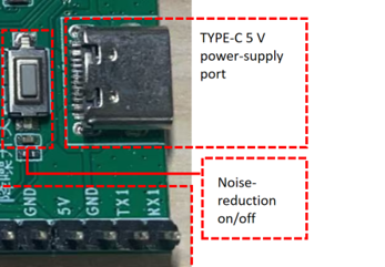
- Comparison between Noise Reduction and No Noise Reduction
The noise reduction feature is enabled by default upon power-up. Press the button once to disable noise reduction, and press again to re-enable it. This allows for direct comparison of audio quality with and without noise reduction, demonstrating both noise suppression effectiveness and audio fidelity.
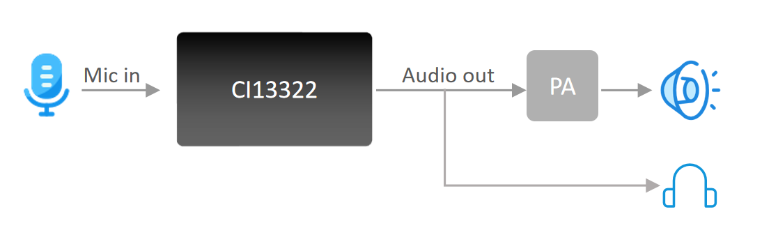
2.3 Complete Product Testing
- For complete product testing, you can integrate the CI-F322GS01S hardware module into your existing product. The connection diagram is as follows:
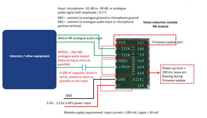
Note: The module requires a 3.3V power supply. For audio input levels and microphone requirements, please refer to the diagram above. It is recommended to read the module specifications CI-F322GS01S before use.
3. Development Preparation
Before starting development, please prepare the following hardware. For mass production, please refer to the Documentation Center Production and contact Chipintelli for production support:
3.1 Hardware Design
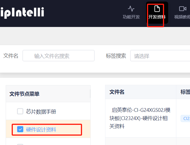
- Hardware Development Resources
Log in to our AI Platform and navigate to: Development Resources → Hardware Design Resources → Chipintelli-CI1332X_Half-Duplex Call Noise Reduction Solution…
-
After downloading the resources, you can directly copy the schematics and PCB designs from the documentation.
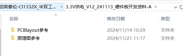
-
For schematic and PCB design considerations, please refer to the checklist provided in the documentation.
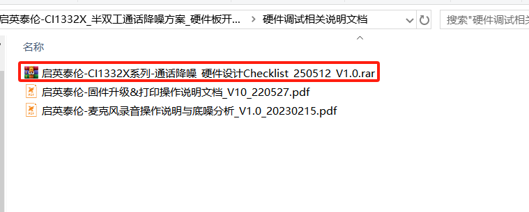
3.2 Hardware Programming
- The following is a serial programming tool (the module comes with call noise reduction firmware by default, for usage please refer to the module specification).
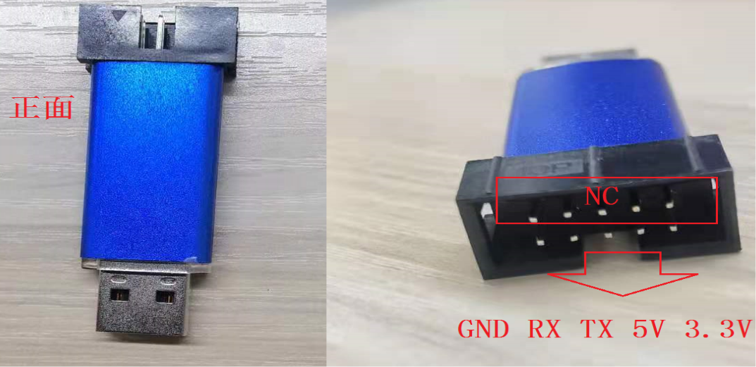
Note: Developers can use a general-purpose serial debug tool for firmware programming and log viewing, or click Purchase Link
Special Note: For stable data transmission, it is recommended to use a serial port with a crystal oscillator. We recommend using CH341 serial port (☞CH340 Official Driver Download)
For firmware programming and printing instructions, please refer to the document “Chipintelli-CI1332X_Half-Duplex Call Noise Reduction Solution…” in the downloaded materials.
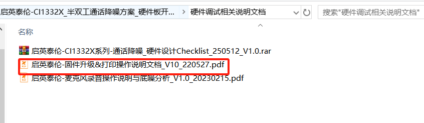
- Audio Capture Board, used for analyzing product noise floor and audio quality
This audio capture board primarily uses I2S for audio capture and UART for analyzing the voice module under test (requires specific software-configured firmware). Refer to quick start guide for more information.
You can also refer to the document “Chipintelli-CI1332X_Half-Duplex Call Noise Reduction Solution…” in the downloaded materials.
3.3 Software Development
Currently not available for external use. For requirements, please contact our business team Chipintelli Business Contact
4. Common Issues and Troubleshooting
4.1 Device Not Responding After Powering On
- Check if the power supply is functioning correctly.
- Verify whether the software is configured for internal or external 1.1V power supply.
- If using an external 1.1V power supply, test if the voltage remains stable.
4.2 Unclear Audio Output
Muffled or unclear audio output, which commonly occurs in downlink solutions. The main causes are: 1. Audio signal amplitude input to the noise reduction IC is too high. 2. Issues with the overall device assembly.
-
Confirm that the audio signal amplitude input to the noise reduction IC is below 0.5V.
-
The default configuration uses a -32dB MIC. If the previously used MIC has a sensitivity lower than -32dB, the output amplitude might be too high, requiring voltage division at the backend.
-
The speaker must be fixed and cannot move, and it is recommended to perform a complete product test.
4.3 Speaker Noise
Specifically for Downlink Solution
-
For walkie-talkie products, ensure the receiving antenna is properly connected. A disconnected antenna might introduce noise.
-
Disconnect the audio output pin of the noise reduction IC from the backend to determine if the noise originates from the IC.
-
Avoid having any capacitors to ground between the noise-reduced audio output and the power amplifier input. Remove any such capacitors for testing if present.
-
Check for hardware circuit design issues, particularly with the AGND pin of the chip. For example, pin 28 of the 13322 must be directly connected to ground without any ferrite beads in between.
-
Ensure the connection point between AGND and GND has 0Ω resistance, with a maximum tolerance of 1Ω.
-
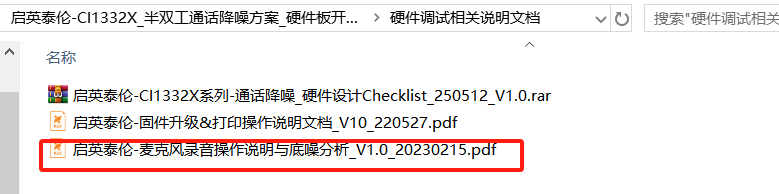
The 4.7μF decoupling capacitors for VCM, MICBIAS, and AVDD must be placed close to the IC. Verify their ground connections. The ground pins of these capacitors are shown in the image below.
4.3 Speaker Pop Noise During Power-Up
Pop noise from the speaker is primarily caused by a sudden transient in the input circuit after the power amplifier is turned on. This typically occurs when the power amplifier turns on before the noise reduction IC initializes.
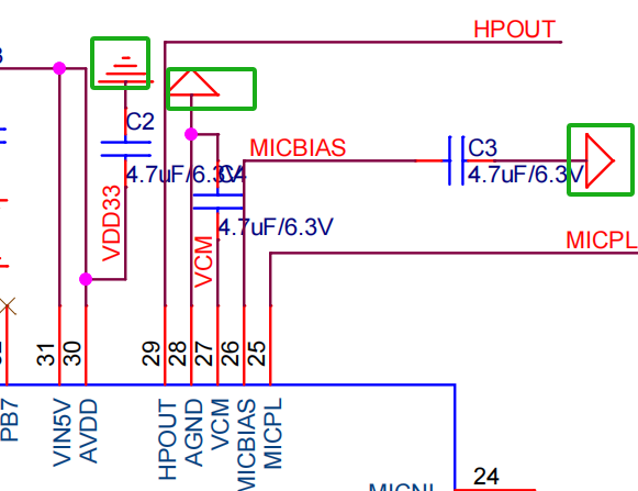
- For fast boot-up, a pull-down resistor must be added to the PA4 (PIN8) of the chip in the hardware design. Without this, the power-up time will be significantly longer, as shown in the diagram below:
- If a pull-down resistor is already connected to PA4, ensure that the power amplifier is not enabled until at least 200ms after power is applied to the voice IC.