CI-F322GS01S Module Datasheet
Module Introduction
Overview
The CI-F322GS01S is a universal, portable, low-power, high-performance AI ENC noise reduction module, with CI13322 as its main chip. It is widely applicable in voice noise reduction scenarios such as walkie-talkies, microphones, and headsets.
Supported noise suppression types include: wind noise, howling, keyboard sounds, traffic noise, music, and crowd noise.
The CI-F322GS01S module features:
- Compact design: Module dimensions of 16mm × 11mm with castellated holes for easy reflow soldering
- Minimal components: Only requires power supply, microphone, and a few external passive components for full functionality
- Simple interfaces: One 3.3V power supply, three UART communication interfaces, one microphone interface, one noise-reduced audio output, and one I2S interface
- Low power consumption: Suitable for energy-efficient or battery-powered products
- High reliability: All BOM components are industrial-grade
Main Chip Introduction
CI13322 is a new generation high-performance neural network intelligent voice chip developed by Chipintelli, integrating Chipintelli’s self-developed BNPU V3.5 and CPU core. With a system frequency up to 210MHz and built-in 288KB SRAM, it features an integrated PMU power management unit, RC oscillator, single-channel high-performance low-power Audio Codec, and multiple peripheral control interfaces including UART, I2C, PWM, and GPIO. The CI13322 chip requires minimal external components, making it highly cost-effective for various intelligent voice product hardware solutions.
Designed to industrial standards, the CI13322 offers excellent environmental reliability with an operating temperature range of -40°C to +85°C, MSL3 moisture sensitivity level, 4KV contact discharge test standard compliance (IEC 61000-4-2), and meets RoHS and REACH environmental standards.
Utilizing Chipintelli’s next-generation BNPU technology, the CI13322 supports neural networks including DNN, TDNN, RNN, and CNN, along with parallel vector operations, enabling high-performance voice recognition, noise reduction, and robust environmental noise suppression. The CI13322 solution also supports multiple global languages including Chinese, English, and Japanese, making it suitable for a wide range of applications including home appliances, lighting, toys, wearables, industrial, and automotive products.
For more detailed information about the CI13322 chip, please visit:
Module Specifications
Physical View
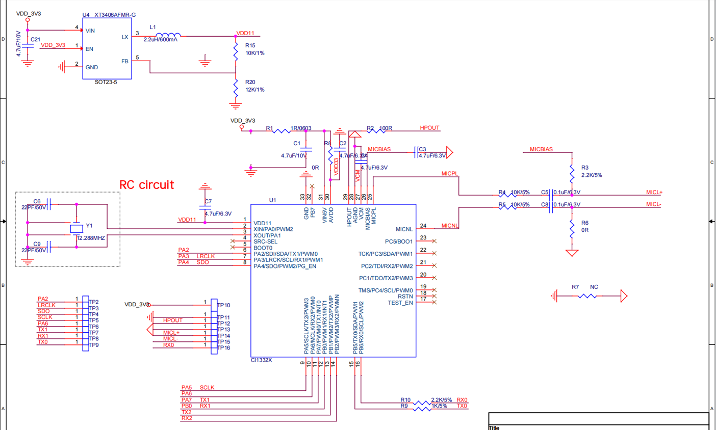
As shown in Figure 2, the CI-F322GS01S module features single-sided SMT assembly with the CI13322 voice processor as the main component. The working flow involves audio input from the microphone, noise reduction processing by the CI13322 IC, and output of the processed audio through the HPOUT pin.
Note: The physical view is for reference only. The silkscreen on components may vary between production batches, but this does not affect module performance. The actual module appearance may vary.
Module Dimensions

Refer to Figure 3 for the dimensional data of the CI-F322GS01S module when designing mechanical enclosures or planning PCB layouts.
Hardware Interface Definition
The CI-F322GS01S module includes the following functional interfaces:
- Single microphone interface: Audio input. Supports common microphone sensitivities: -32dB, -38dB, -42dB, -58dB.
- Noise-reduced audio output: HPOUT provides processed audio output, typically connected to the product’s audio input interface.
- UART interface: UART0 is used for firmware updates.
- Other interfaces: Refer to the pin function definition table below.
Pin functions are defined in Table 1:
| Pin | Name | I/O Type | Drive Capability | Default State | Function |
|---|---|---|---|---|---|
| 1 | VDD33 | P | - | - | 3.3V Power Supply |
| 2 | GND | P | - | - | Ground |
| 3 | HPOUT | O | - | - | DAC Output |
| 4 | AGND | P | - | - | Analog Ground |
| 5 | MICL+ | - | - | - | Microphone Positive |
| 6 | MICL- | - | - | - | Microphone Negative |
| 7 | PB6 | IO | 4mA | IN, T+U | ● GPIO PB6 (default) ● UART0_RX ● I2C_SCL ● PWM2 ● PWMN |
| 8 | PB5 | IO | 4mA | IN, T+U | ● GPIO PB5 (default) ● UART0_TX ● I2C_SDA ● PWM1 ● PWMP |
| 9 | PB0 | IO | 4mA | IN, T+D | ● GPIO PB0 (default) ● PWM1 ● RX1 ● INT1 |
| 10 | PA7 | IO | 4mA | IN, T+D | ● GPIO PA7 (default) ● PWM0 ● TX1 ● INT0 |
| 11 | PA6 | IO | 4mA | IN, T+D | ● GPIO PA6 (default) ● I2S_MCLK ● - ● UART2_RX ● PWM0 |
| 12 | PA5 | IO | 4mA | IN, T+D | ● GPIO PA5 (default) ● I2S_SCLK ● - ● UART2_TX ● PWM3 ● PWMN0 |
| 13 | PA4 | IO | 4mA | IN, T+U | ● GPIO PA4 (default)/PG_EN (determines programming mode based on power-on level, high level enables programming) ● I2S_SDO ● - ● - ● PWM2 ● PWMP |
| 14 | PA3 | IO | 4mA | IN, T+D | ● GPIO PA3 (default) ● I2S_LRCLK ● I2C_SCL ● UART1_RX1 ● PWM1 ● PWMN |
| 15 | PA2 | IO | 4mA | IN, T+D | ● GPIO PA2 (default) ● I2S_SDI ● I2C_SDA ● UART1_TX ● PWM0 ● PWMP |
Symbol definitions in the table:
I = Input
O = Output
IO = Bidirectional
P = Power or Ground
T+D = Tristate with pull-down
T+U = Tristate with pull-up
OUT = Power-on default is output mode
IN = Power-on default is input mode
Electrical Characteristics
| Parameter | Condition | Min | Typ | Max | Unit | Note |
|---|---|---|---|---|---|---|
| Module Supply Voltage | / | 3.15 | 3.3 | 3.45 | V | |
| Module Operating Current | / | / | 26 | / | mA | |
| Chip I/O Voltage | / | 3.15 | 3.3 | 3.45 | V | |
| Module UART Interface Voltage | / | 3.15 | 3.3 | 3.45 | V |
Noise Reduction Specifications
| Parameter | Description | Min | Typ | Max | Unit | Note |
|---|---|---|---|---|---|---|
| Signal-to-Noise Ratio | Ratio of voice to background noise | ≥-5 | ≥0 | / | dB | / |
| Noise Suppression | Maximum introduced noise | / | / | ≤80 | dB | / |
| Power-on Time | Time from power-on to noise-reduced audio output | / | <200 | / | ms | / |
| Processing Latency | Time from audio input to noise-reduced audio output | / | 78 | / | ms | / |
| Pickup Distance | Distance from speaker to microphone | / | ≤10 | / | cm | Contact our sales or FAE for other parameters |
| Microphone | Recommended omnidirectional microphone sensitivity | -58 | / | -32 | dB | Contact our sales or FAE for other parameters |
| Input Amplitude | Maximum input amplitude when directly connecting audio signal | / | 0.5 | 0.7 | V | Contact our sales or FAE for other parameters |
SNR Improvement Capability
Signal-to-Noise Ratio (SNR) improvement in different environments, with an average improvement of about 40dB.
| Test Environment | Original Audio SNR (dB) | Processed Audio SNR (dB) |
|---|---|---|
| White Noise | 10.85 | 43.95 |
| Marketplace | 4.30 | 47.34 |
| Supermarket | 5.39 | 47.04 |
| Wind Noise | 4.13 | 49.88 |
| Construction Site | 7.46 | 39.25 |
| Traffic Intersection | 7.37 | 52.11 |
| Hair Salon | 5.77 | 49.39 |
| Bubble Tea Shop | 6.39 | 49.46 |
| Shopping Mall | 3.55 | 42.08 |
| Arcade | 6.30 | 48.65 |
| Average | 6.15 | 46.92 |
Environmental Specifications
| Parameter | Min | Typ | Max | Unit | Note |
|---|---|---|---|---|---|
| Operating Temperature | -25 | 25 | 85 | °C | / |
| Storage Temperature | -40 | 25 | 100 | °C | / |
| Storage Humidity | 0% | / | 5% | RH | / |
Module Application
Power-up and Startup
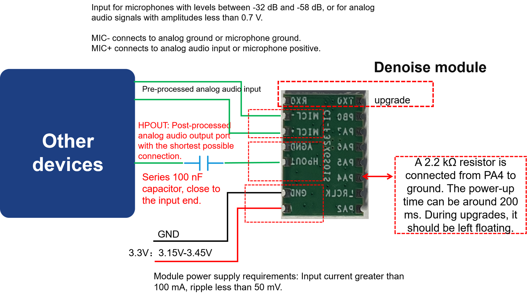
When using the module, connect the 3.3V power supply and microphone, then connect HPOUT to the product’s audio input interface (e.g., walkie-talkie microphone input). The module will start upon power-up. Speak into the microphone, and the processed audio will be output from HPOUT. The UART0 interface will display debug information during this process. Note that the module’s UART interface operates at 3.3V logic level; level shifting is required when interfacing with 5V systems.
The 3.3V power supply must provide a stable 100mA current with ripple below 50mV.
Module Application Connection
The module can be integrated into existing products as shown below:
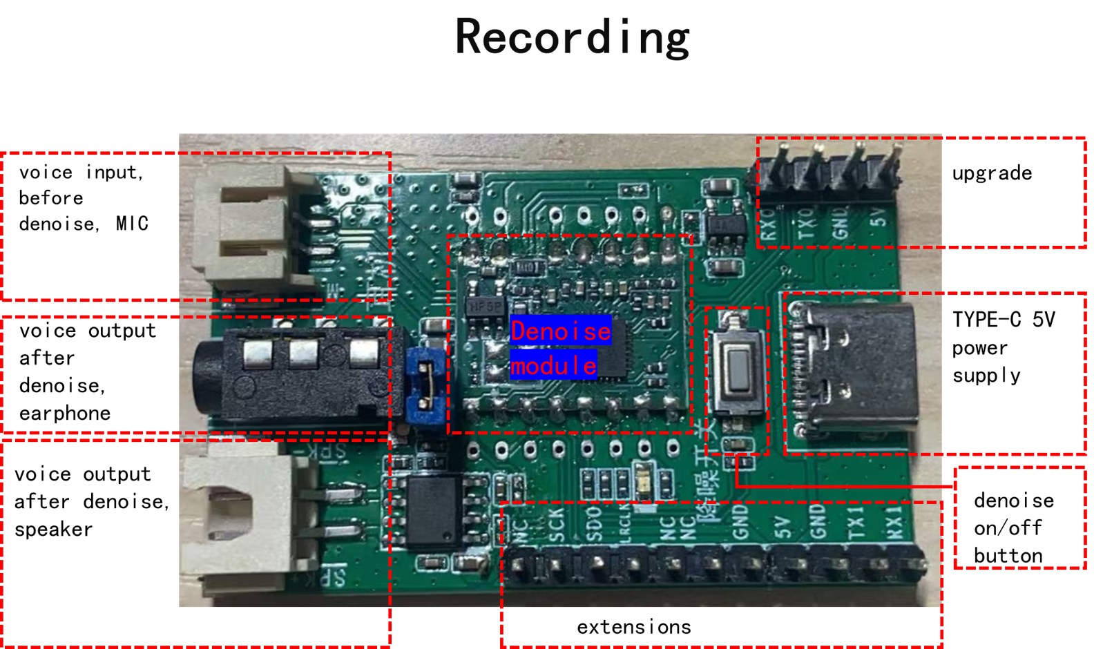
Demo Board Operation
A noise reduction module demo board (Model: CI-F32XGS01S_MB) is available for purchase on our platform.
Software Development
The default firmware included with the module is for initial evaluation. For custom development, please contact our FAE team.
Firmware Programming
Pre-programming Preparation
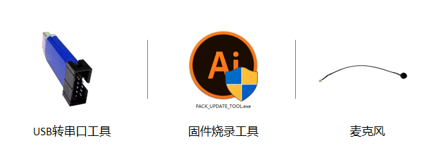
Before programming the module, prepare the following items:
- Module to be programmed
- USB-to-UART adapter
- Firmware programming tool (pack_update_tool.exe)
- Firmware file (*.bin)
- Microphone
- Jumper wires
Hardware Connection and Programming
Using the USB-to-UART adapter as an example, connect the power, ground, and UART pins to the corresponding module pins (note that the adapter’s RXD and TXD should connect to the module’s UART0_TX and UART0_RX respectively).
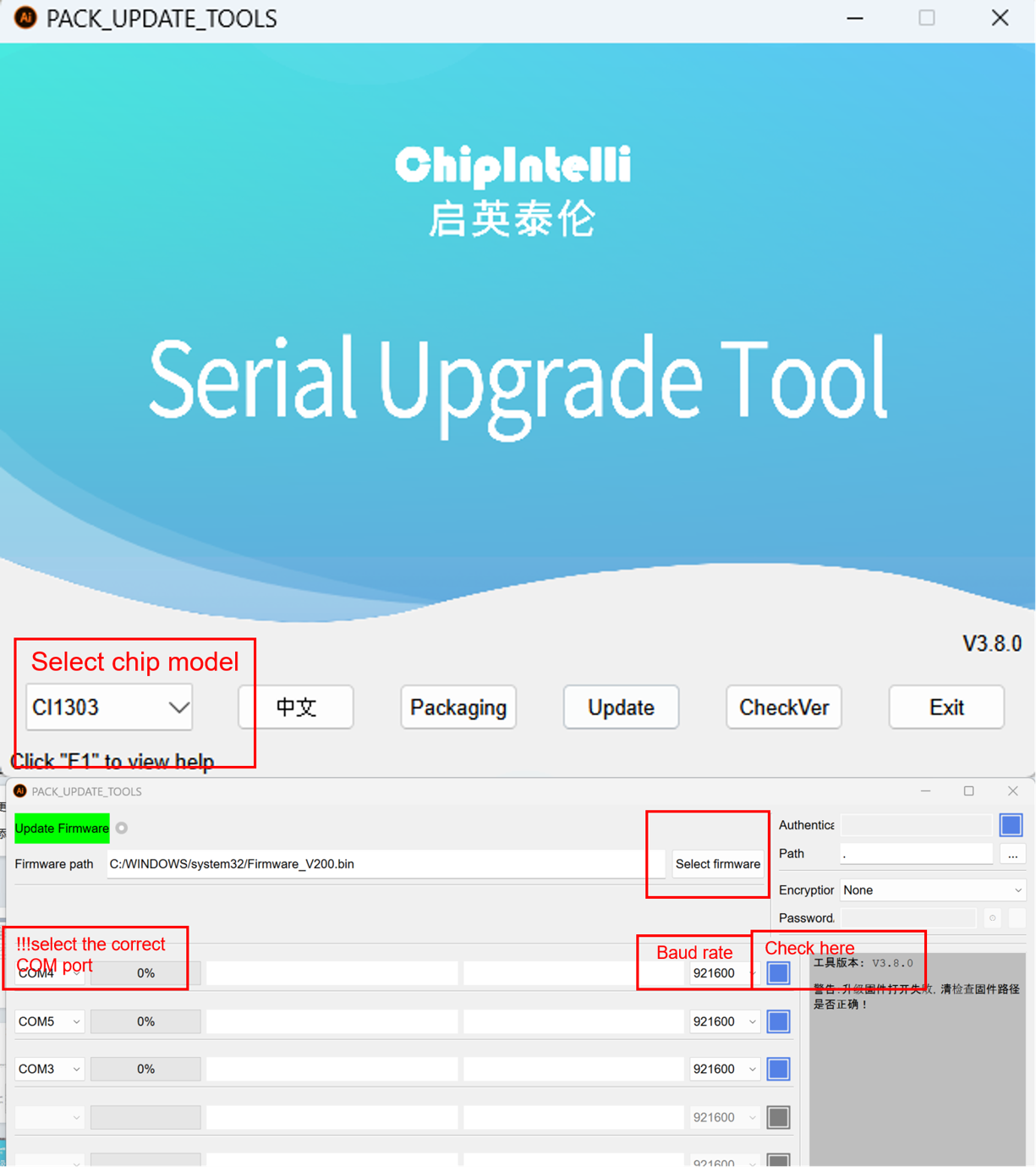
Open the firmware programming tool (PACK_UPDATE_TOOL.exe, available in the SDK development package under CI13LC_SDK\tools), select the correct chip model, click the firmware update button, select the prepared firmware file, and choose the correct COM port assigned to the USB-to-UART adapter. After preparation, power cycle the module to enter programming mode and download the firmware. If the USB-to-UART adapter is not recognized, install the appropriate drivers on your computer.
Post-programming Functional Test
After successful programming, test the module’s functionality to verify the firmware. Connect a microphone to the module and connect HPOUT to the product’s audio input. Power on and speak into the microphone; the processed audio should be output from HPOUT. If functioning correctly, the programming was successful. If not, troubleshoot accordingly.
Troubleshooting
This section lists common issues and solutions when using the module.
- Module cannot be programmed or firmware updated.
Check the following:
- Ensure TX, RX, and GND are connected before powering on with 3.3V.
- Verify UART pin connections (TX/RX not swapped), USB-to-UART driver installation, and correct COM port selection.
- Check if pin 13 (PA4) is floating. It must be floating during programming.
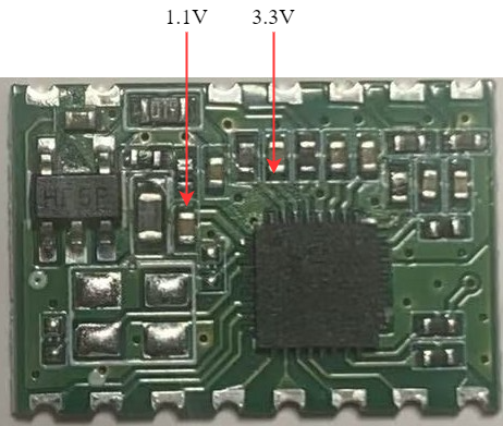
- If issues persist, measure the module’s power supply voltages (3.3V, 1.1V) using a multimeter. Refer to the hardware measurement points below. If voltage or crystal issues are found, replace the module or repair the hardware. If problems continue, contact technical support.
- No noise-reduced audio output after programming and power-up.
Check the following:
- Confirm the programmed firmware is compatible with the board.
- Verify HPOUT is properly connected to the product.
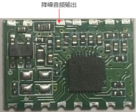
Use an oscilloscope to measure the noise-reduced audio output. Speak into the microphone after power-up; the processed audio should be present at HPOUT. If no output is detected, verify the firmware. If output is present but not functioning as expected, check other points in the signal chain. If issues persist, contact technical support.
Additional Application Notes
Due to the chip’s high ESD rating and the module’s design for user expansion, ESD protection devices are not included on the module. For products requiring high ESD protection, add ESD devices to the main board to ensure product reliability. When handling or soldering, wear an anti-static wrist strap or gloves.
Ensure correct connections for the microphone, power supply, and UART interfaces.
Note that the module’s UART interface operates at 3.3V logic level. Use a 3.3V-compatible UART for communication. For software debugging, use a USB-to-UART adapter with the SDK. Add UART print commands in the software, compile the firmware, program it, and verify functionality.
Production Guide, Storage, and Ordering Information
Production and Storage Guidelines
-
The CI-F322GS01S module must be assembled using SMT equipment. After opening the packaging, complete SMT assembly within 24 hours or reseal in a moisture barrier bag.
-
Storage conditions for CI-F322GS01S module:
-
Modules in vacuum-sealed moisture barrier bags can be stored at -40°C to +100°C and 0% to 85% relative humidity.
-
The moisture barrier bag contains a humidity indicator card as shown below:

- If the humidity indicator card shows the following color changes, bake the modules according to the specified parameters:
-
If the 30%, 40%, and 50% rings are all blue when opening the vacuum bag, bake for 2 hours.
-
If the 30% ring turns pink, bake for 4 hours.
-
If both 30% and 40% rings turn pink, bake for 6 hours.
-
If 30%, 40%, and 50% rings all turn pink, bake for 12 hours.
- Baking parameters:
-
Baking temperature: 125±5°C
-
Alarm temperature: 130°C
-
Baking cycles: 1
-
Cool naturally until module temperature is below 36°C before SMT assembly
-
If more than 12 hours elapse after baking without assembly, re-bake the modules.
-
Implement ESD protection throughout the assembly process. Operators should wear anti-static gloves/wrist straps.
-
For optimal production yield, perform visual inspection and AOI testing on all assembled modules, paying attention to temperature profile, pick-and-place method, and component orientation.
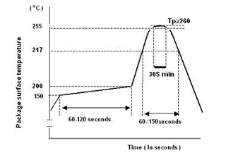
Recommended Reflow Profile
Packaging and Ordering Information
| Model | Packaging | Modules per Tray | Modules per Pack | Modules per Carton |
|---|---|---|---|---|
| CI-F322GS01S | Tray + ESD Bag + Carton | 140pcs | 15 trays (2,100pcs) | 3 packs (6,300pcs) |
Purchasing and Technical Support
To purchase samples, visit ☞Sample Purchase or click ☞Samples and Bulk Purchasing for more information.
For technical support, visit the ☞Chipintelli AI Platform.