Inter-IC Sound (I2S)
1. Introduction
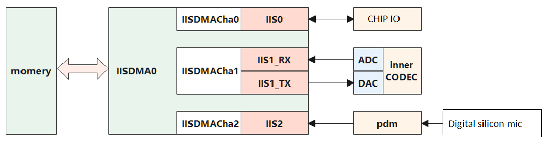
I2S System Block Diagram
- I2S is a digital audio interface for transferring audio data between devices, interfacing with external stereo audio CODECs at 16/20/24/32‑bit depths.
- CI13XX provides three IIS peripherals (IIS0~IIS2). IIS0 is a general‑purpose interface supporting TX and RX. IIS1 is an internal dedicated interface, also supporting TX/RX: the TX unit is dedicated to the on‑chip CODEC DAC and the RX unit to the on‑chip CODEC ADC. IIS2 is a receive‑only interface used to connect the on‑chip PDM module.
- CI13XX includes a dedicated DMA controller for IIS (IISDMA0) to transfer data between memory and the IIS peripherals. All IIS peripherals share IISDMA0 via different channels.
2. Features
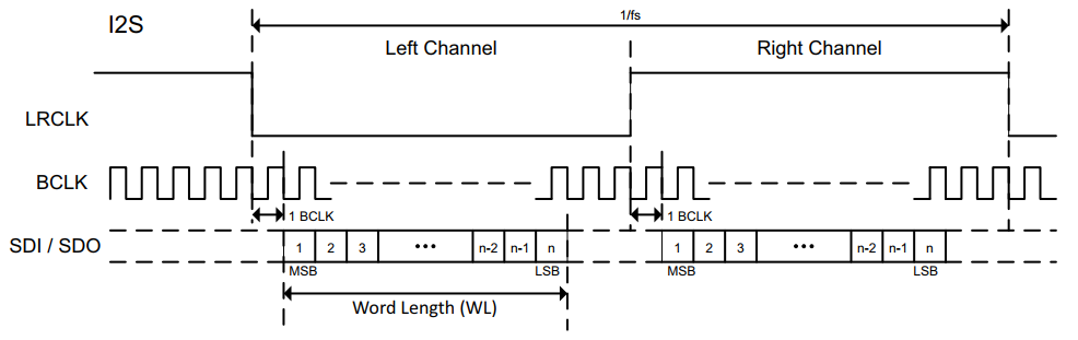
- I2S signals include MCLK, SCK, LRCLK, SDI, and SDO.
- MCLK: Master clock, typically 128/192/256/384 times the audio sample rate (LRCLK frequency).
- SCK: Serial bit clock; one data bit per SCK cycle.
- LRCLK: Frame clock used to switch left and right channel data.
- In I2S format, LRCLK=0 indicates left channel; LRCLK=1 indicates right channel for the current frame.
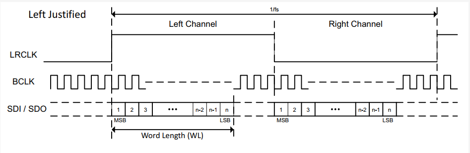
- In left/right‑justified formats, LRCLK=0 indicates right channel; LRCLK=1 indicates left channel for the current frame.
- SDI/SDO: Serial data input/output for audio data transfer.
- LRCLK to SCK ratio configurable as 1:32 or 1:64. TX path configured via
iis_tx_config, RX path viaiis_rx_config. - Data format configurable as I2S, left‑justified, or right‑justified. TX via
iis_tx_config, RX viaiis_rx_config. - Data width configurable as 16/20/24/32 bits. TX via
iis_tx_config, RX viaiis_rx_config. - In mono mode, TX can duplicate mono data to both channels; RX can merge L/R into mono.
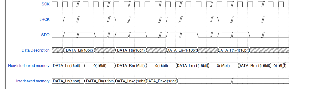
- With 16‑bit sample width, channel merge is supported; see the diagram below.
 {:.center }
- Left/right channel swap is supported for both RX and TX. Configure RX swap with
iis_rx_configand TX swap withiis_tx_config. - RX and TX paths are fully independent.
- Mute supported: RX via
iis_rx_mute; TX viaiis_tx_r_mute/iis_tx_l_mute. - Channel count configurable: RX mono/stereo via
iis_rx_config; TX mono/stereo viaiis_tx_config.
3. I2S Timing
3.1 Clock Calculations
- Example: sample rate 16 kHz (LRCK), MCLK = 256×, sample width 16‑bit, SCK/LRCK = 64
- MCLK = 16 kHz × 256 = 4.096 MHz ≈ 4 MHz
- BCLK = 64 × 16 kHz = 1.024 MHz ≈ 1 MHz
- Verify pin clocks using an oscilloscope
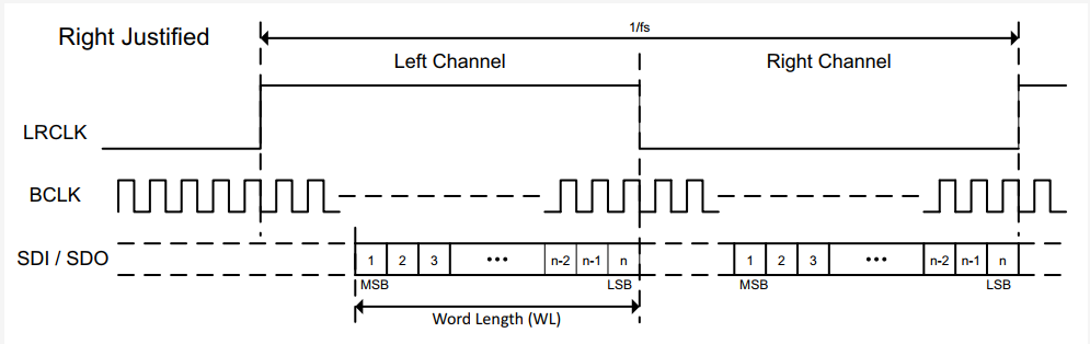
3.2 Timing Diagrams
- (1) I2S format
- (2) Left‑justified format
- (3) Right‑justified format
4. API List
| Function Name | Description |
|---|---|
| iis_rx_config | Initialize RX mode |
| iis_rx_mute | RX mute |
| iis_tx_config | Initialize TX mode |
| iis_tx_r_mute | TX right‑channel mute |
| iis_tx_l_mute | TX left‑channel mute |
| iis_rx_enable | Enable RX |
| iis_tx_enable | Enable TX |
5. Example
For examples using IIS and IISDMA, see Audio System Management.