Gain Adjustment
Gain Control
1. Overview
- Gain is the ratio of output signal amplitude to input signal amplitude, representing an amplifier’s amplification capability, typically expressed in dB. For example, MIC input and raw playback audio may have small amplitudes; adjusting the CODEC gain amplifies them. This document describes CODEC gain control as well as gain control for the AEC reference signal.
2. dB Units
- The unit dB can represent multiple concepts, commonly including dB for amplification factor and dB for speech signal amplitude (dBFS).
- Other dB-related units include dBSPL, dBm, dBu, and dBV. dBSPL is a unit of sound pressure (used by decibel meters); dBm represents power in dB, where power dB uses 10·log rather than 20·log.
2.1 dB for Amplification Factor
-
For multi-stage amplification, when expressed in dB, the overall amplification (in dB) is the sum of each stage’s amplification (in dB). Very large amplification factors can be conveniently represented using smaller dB values.
-
The formula for converting amplification factor to dB is as follows:

- Common correspondences between amplification factor and dB are shown below. For example, a 1000× gain corresponds to 60 dB:
| Amplification Factor | dB |
|---|---|
| 1 | 0 |
| 2 | 6 |
| 10 | 20 |
| 100 | 40 |
| 1000 | 60 |
2.2 dB for Speech Signal Amplitude
- Speech amplitude can be represented numerically or in dB. The full term is dBFS (Decibels Full Scale). Computing amplitude dB is more complex than amplification factor dB; formulas vary with system bit depth.
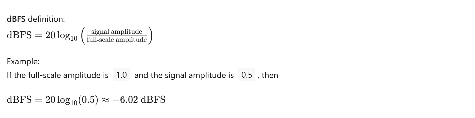
- For example, in a 16‑bit system, ‘sample’ represents the sample value, and 65536 equals 2^16. In systems with different bit depths, the denominator for sample normalization differs. The amplitude dB formula is as follows:

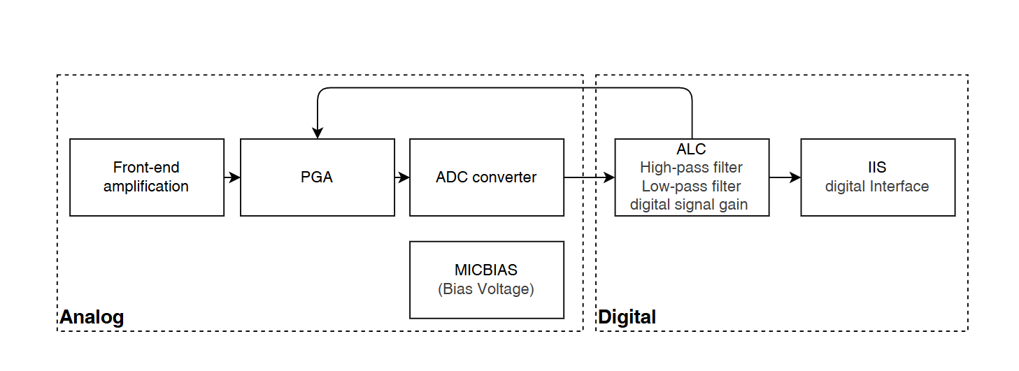
3. Audio CODEC ADC Architecture
- The CODEC input is the MIC output signal. The analog MIC signal has a relatively small amplitude and needs to be amplified by the CODEC, converted to digital by the ADC, filtered and processed, and then transmitted via a digital interface to the controller. The CODEC consists of two parts: analog and digital.
-
The analog part includes pre‑amplification, PGA, and ADC; some CODECs also provide MICBIAS. The digital part includes ALC (Automatic Level Control), high‑pass and low‑pass filters, digital gain, and the digital interface for external transmission.
-
The analog and digital sections are not completely independent. For example, ALC evaluates the digitized signal after ADC and checks whether the current amplitude meets the configured level. If it does, the PGA gain remains unchanged; otherwise, within allowed limits, ALC adjusts the PGA gain so the signal amplitude stays within the target level range.
4. CODEC ADC Gain
- The CODEC provides three gain stages: pre‑gain, PGA, and digital gain. Pre‑gain and PGA are analog amplification stages. Digital gain uses the CODEC’s internal 24‑bit digital processing and is not a simple multiply/divide on 16‑bit samples.
4.1 Pre‑Gain (MIC Gain)
- MIC pre‑gain is also a programmable gain. Compared to PGA, pre‑gain has coarser steps and a narrower range. The available settings are:
// Located in #include "ci130x_codec.h"
/**
 * @brief Inner CODEC MIC gain configuration
 */
typedef enum
{
    INNER_CODEC_MIC_AMP_0dB = 0,
    INNER_CODEC_MIC_AMP_6dB,
    INNER_CODEC_MIC_AMP_9dB,
    INNER_CODEC_MIC_AMP_12dB,
    INNER_CODEC_MIC_AMP_16dB,
    INNER_CODEC_MIC_AMP_20dB,
} inner_codec_mic_amplify_t;
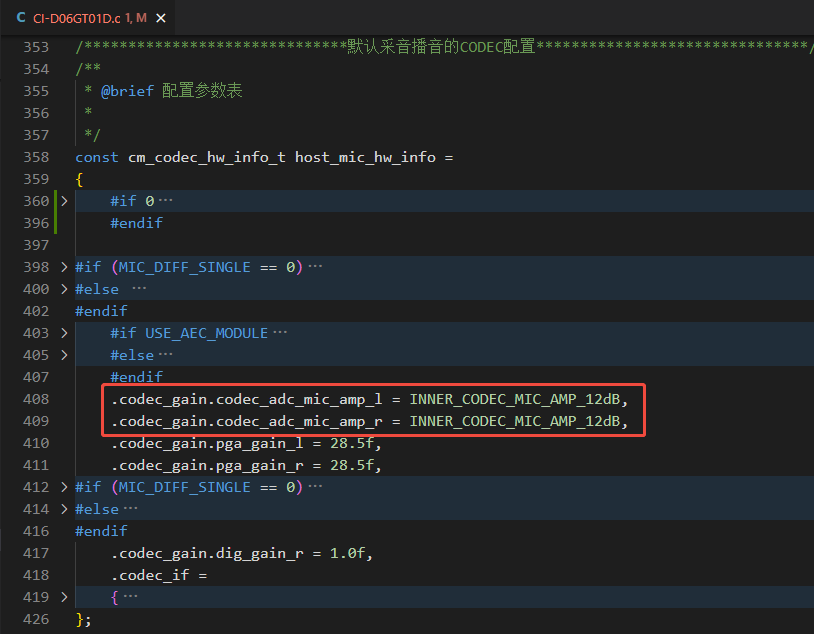
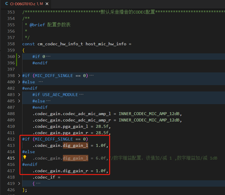
- Left/right microphones can use different pre‑gain values. For example, modify parameters in the board file
CI-D06GT01D.c(pathCI130X_SDK\driver\boards\CI-D06GT01D.c):
4.2 PGA Gain
-
PGA is a Programmable Gain Amplifier. Two modes are supported: fixed gain and automatic gain control. If the recording ALC feature is used, PGA must operate in automatic gain mode.
-
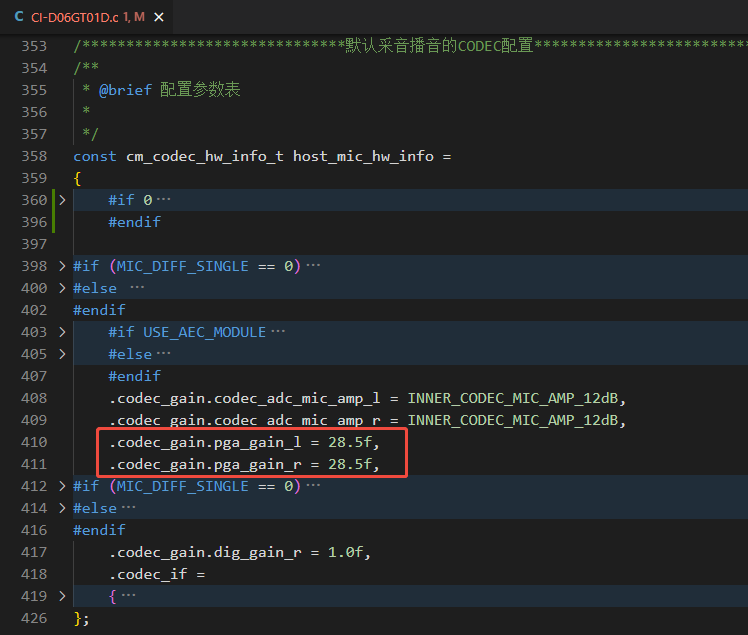
The PGA gain range is −18 dB to 28.5 dB with 1.5 dB steps.
-
Left/right microphones can use different PGA gains. For example, set a fixed PGA gain by modifying parameters in the board file
CI-D06GT01D.c:
- Alternatively, set a fixed PGA gain via the audio manager API:
// Located in #include "codec_manager.h"

int cm_set_codec_adc_gain(int codec_index, cm_cha_sel_t cha, int gain);
- Or set a fixed PGA gain via the codec driver API:
// Located in ci130x_codec.c

/**
 * @brief Set fixed PGA gain for the CODEC
 *
 * @param gain Left channel PGA gain
 */
void inner_codec_set_pga_gain(inner_codec_cha_sel_t cha, int32_t ALC_Gain);
4.3 Digital Gain
-
Digital gain has a very wide adjustable range. When the
digt_gainregister is 195, the gain is 0 dB; each increment/decrement of 1 changes the digital gain by ±0.5 dB. The digital gain range is −97 dB to 30 dB. -
Left/right microphones can use different digital gains. For example, modify parameters in the board file
CI-D06GT01D.c:
- Or set digital gain via the codec driver API:
// Located in "ci130x_codec.c"

/**
 * @brief Adjust CODEC ADC digital gain (195 = 0 dB; ±1 step = ±0.5 dB)
 *
 * @param gain Left channel gain value
 */
void inner_codec_adc_dig_gain_set(inner_codec_cha_sel_t cha, int32_t gain);
5. CODEC ALC
5.1 ALC Principle
-
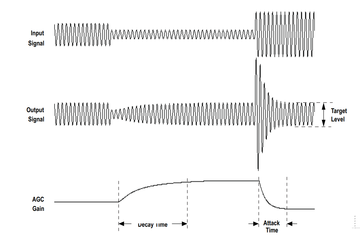
ALC stands for Automatic Level Control. Its goal is to adjust the output signal amplitude to stay near the configured level.
-
The ALC workflow is illustrated below:
-
(1) If the input amplitude is near the configured level, ALC does not change the PGA gain.
-
(2) If the input amplitude is below the level, ALC increases the PGA gain step by step according to
decaytimeuntil the output reaches the level vicinity or the PGA gain hits its maximum. For example, withdecaytime = 2 ms, ALC increments the PGA gain by one step every 2 ms. -
(3) If the input amplitude is above the level, ALC decreases the PGA gain step by step according to
attacktime.
5.2 ALC Parameters
5.2.1 Time‑related Parameters
holdtime, decaytime, attacktime
- (1)
holdtime: Duration to hold the gain unchanged. Even if ALC decides to adjust PGA gain, ifholdtimeis 4 ms, the PGA will start adjusting only after 4 ms. - (2)
decaytime: Time per step when increasing PGA gain. -
(3)
attacktime: Time per step when decreasing PGA gain. -
The ALC action for decreasing PGA gain is shown below. The gain decreases step by step according to
attacktime. Increasing behaves similarly:
- You can adjust these three time parameters in
ci130x_codec.c:
// Located in ci130x_codec.c

#define ALC_HOLD_TIME   INNER_CODEC_ALC_HOLD_TIME_2MS
#define ALC_DECAY_TIME  INNER_CODEC_ALC_DECAY_TIME_2MS
#define ALC_ATTACK_TIME INNER_CODEC_ALC_ATTACK_TIME_2MS
5.2.2 Level‑related Parameters
low_8bit_maxlevel, low_8bit_minlevel, high_8bit_maxlevel, high_8bit_minlevel
- Configure ALC levels by modifying the parameters in
ci130x_codec.c:
// Located in ci130x_codec.c

#define ALC_LOW_8_BIT_MAX_LEVEL     ((uint8_t)(INNER_CODEC_ALC_LEVEL__6dB >> 0))
#define ALC_HOGH_8_BIT_MAX_LEVEL    ((uint8_t)(INNER_CODEC_ALC_LEVEL__6dB >> 8))
#define ALC_LOW_8_BIT_MIN_LEVEL     ((uint8_t)(INNER_CODEC_ALC_LEVEL__7_5dB >> 0))
#define ALC_HOGH_8_BIT_MIN_LEVEL    ((uint8_t)(INNER_CODEC_ALC_LEVEL__7_5dB >> 8))
5.2.3 Limiting ALC’s PGA Adjustment
maxgain, mingain
-
These two parameters limit ALC’s ability to adjust the PGA, i.e., the maximum and minimum gain steps ALC can reach.
-
Configure these limits by modifying parameters in
ci130x_codec.c:
// Located in ci130x_codec.c

#define ALC_PGA_MAX_GAIN    INNER_CODEC_ALC_PGA_MAX_GAIN_28_5dB
#define ALC_PGA_MIN_GAIN    INNER_CODEC_ALC_PGA_MIN_GAIN__18dB
5.2.4 Enabling/Disabling ALC
- Modify
ci130x_codec.cto enable/disable ALC. When ALC is enabled, PGA gain is controlled automatically. When disabled, PGA gain is the value configured in section 4.2 “PGA Gain”.
// Located in ci130x_codec.c

#define ALC_AGC_FUNC_SEL    ENABLE   // ENABLE: enable ALC; DISABLE: disable ALC
- Or call the API to enable/disable ALC:
// Located in #include "codec_manager.h"

int cm_set_codec_alc(int codec_index, cm_cha_sel_t cha, FunctionalState alc_enable);
5.2.5 ALC Zero‑Cross Detection
-
Zero‑cross detection updates the gain at the signal’s zero‑crossing points rather than at arbitrary times, which helps maintain signal quality.
-
Enable/disable zero‑cross detection in
ci130x_codec.c:
// Located in ci130x_codec.c

#define ALC_ZERO_CROSS  INNER_CODEC_GATE_DISABLE  // Zero‑cross detection disabled by default
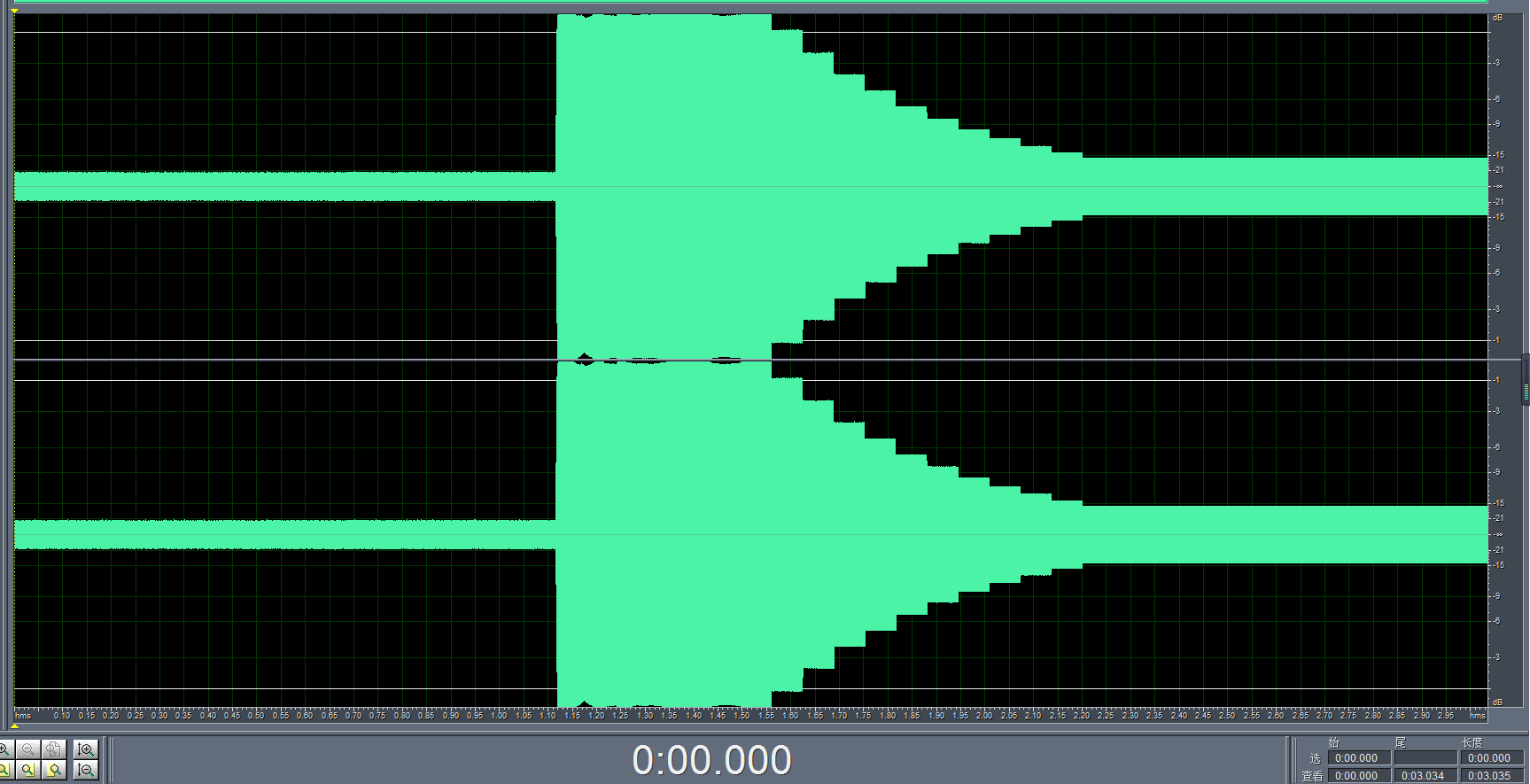
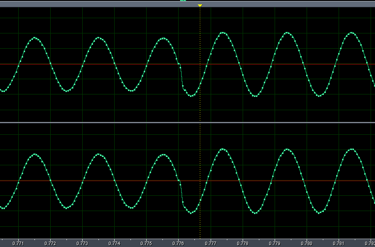
- The following shows the waveform when zero‑cross detection is enabled and gain increases:
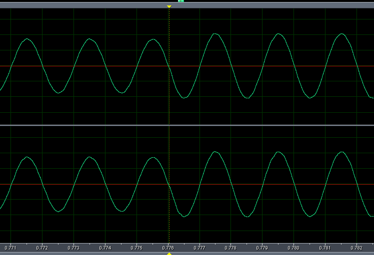
- The following shows the waveform when zero‑cross detection is disabled and gain increases:
5.2.6 ALC Noise Gate
-
The noise gate treats inputs below the configured noise threshold level as noise and avoids amplification. Inputs above the threshold are treated as valid voice signals and processed normally by ALC.
-
Configure the noise gate in
ci130x_codec.c:
// Located in ci130x_codec.c

#define ALC_NOISE_GATE  INNER_CODEC_GATE_DISABLE // Noise gate switch
#define ALC_NOISE_GATE_SET  INNER_CODEC_NOISE_GATE_THRE_45dB // Noise threshold setting
6. CODEC DAC Gain
-
For CODEC DAC gain, there are typically two parts: digital gain and
hpoutgain. Digital gain is usually set to mute, and applications adjust playback volume viahpoutgain. -
Set
hpoutgain using the following function:
// Located in #include "codec_manager.h"

int cm_set_codec_dac_gain(int codec_index, cm_cha_sel_t cha, int gain);