CI13322 Development Board Kit Description
Overview
The CI13322 development board (model: CI-F32XGT01D, hereinafter referred to as the development board) is equipped with Chipintelli’s CI13322 voice recognition chip. With rich peripheral circuits and modules, it enables rapid development of various voice solutions. Whether for voice wake-up, voice control, or voice playback, the development board provides powerful support to help developers efficiently implement their voice applications.
Main Resources of the Development Board
The development board includes the following resources:
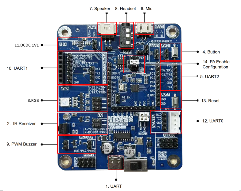
| No. | Interface Name | Function Definition | Description |
|---|---|---|---|
| 1 | USB-to-UART | TYPE-C interface | Firmware programming UART0 communication USB power input |
| 2 | Power switch | \ | Main power switch of the development board |
| 3 | Infrared transmit/receive circuit | IR-TX/PB0 IR-RX/PB1 |
IR-TX – infrared transmit IR-RX – infrared receive |
| 4 | RGB LED | G/PWM2 R/PWM1 B/PWM0 |
G/PWM2 – green LED R/PWM1 – red LED B/PWM0 – blue LED |
| 5 | Key circuit | Normal key | PC5 – key shorted, active low |
| 6 | UART2 / GPIO header | PC3 PC2/RX2 PC1/TX2 PC4 GND 3V3 |
PC3 – general-purpose IO PC2/RX2 – UART2 RX PC1/TX2 – UART2 TX PC4 – general-purpose IO GND – ground 3V3 – 3.3 V power |
| 7 | Microphone input | MIC+ MIC- |
MIC+ – positive terminal of left microphone MIC- – negative terminal of left microphone |
| 8 | Speaker interface | SPK+ SPK- |
Class-A power amplifier, supports 8 Ω / 2 W speaker SPK+ – speaker positive SPK- – speaker negative |
| 9 | Headphone jack | \ | Maximum output power 40 mW, supports 32 Ω headphones |
| 10 | Buzzer interface | BUZ/PA7/PWM0 | BUZ/PA7/PWM0 – buzzer control interface |
| 11 | IIS / UART1 header | MCK SCK SDO LRCK SDI NC GND RX1 TX1 GND 5V |
MCK – IIS MCLK clock SCK – IIS SCLK clock SDO – IIS data output SDI – IIS data input LRCK – IIS left/right channel select GND – ground RX1 – UART1 RX TX1 – UART1 TX GND – ground 5V – 5 V power |
| 12 | External 1.1 V power | \ | Short the jumper cap to use an external 1.1 V power supply. Using an external DC-DC can reduce the chip’s power consumption. |
| 13 | UART0 | RX0 TX0 GND 5V |
RX0 – UART0 RX TX0 – UART0 TX GND – ground 5V – 5 V power Note: UART0 and the USB-to-UART share the same UART. To use this UART0 header, you need to remove the jumpers for the USB-to-UART. |
| 14 | Reset button | \ | Press to reset the chip, can be used for program debugging or firmware download |
| 15 | Power amplifier enable configuration | PA4 PC4 PB7 |
PA4 – EN shorted PC4 – EN shorted PB7 – EN shorted Any one of the three can be used to control the amplifier enable, active low |
For more detailed information about the development board application, please refer to the schematic file below:
☞Development Board Schematic Data
Development Board Accessories
The CI-F32XGT01D package contains the following accessories:
| Name | Purpose | Quantity | Included |
|---|---|---|---|
| CI-F32XGT01D | Development board | 1 | ✓ |
| Microphone | Sound pickup | 1 | ✓ |
| Speaker | Voice playback | 1 | ✓ |
| UART debug tool | Debug communication | 1 | ✓ |
| TYPE-C cable | Firmware programming USB power |
2 | ✓ |
| MIC array board | Development & debugging | 1 | ✓ |
| Dupont wires | Development & debugging | 8 | ✓ |
Application Example
The CI-F32XGT01D development board kit is pre-flashed with factory firmware by default and can implement standard voice recognition and wake-up.
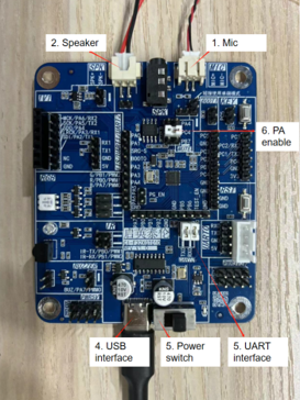
Connect the development board as shown below, turn on the power (the switch position near the USB port is ON), and you will hear the standard firmware voice prompts.
- Connect the TYPE-C USB cable to the USB interface labeled 4 in Figure 3.
- Connect the microphone to the microphone interface labeled 1 in Figure 3 (pay attention to microphone polarity: the red wire is positive, the black wire is negative; match the red wire to MIC+ and the black wire to MIC- according to the silkscreen).
- Connect the speaker to the speaker interface labeled 2 in Figure 3.
- Short the UART0 jumper at position 3 in Figure 3.
Note: The standard firmware on the development board uses a dual-microphone firmware. Therefore, both microphones need to be connected.

Command Words and Corresponding Playback for the Standard Development Board
Before shipment, the standard development board is programmed with standard firmware. When using it, you need to first say the wake word “Hello Jenny”. After you hear the response “I am here”, you can then say other command words. When you hear “Thank you for using” , you need to say “Hello Jenny” again to wake it up.
The table below shows the command words corresponding to one of our standard firmware versions:
Note: Some command words may be removed or added as needed without further notice.
| Command Word | Corresponding Playback | Command Word | Corresponding Playback |
|---|---|---|---|
| Hello Jenny | I am here | 30 Degree | OK, 30 Degree |
| Turn on AC | okay, Turn on AC | Turn on lights | okay, Turn on lights |
| Turn off AC | okay, Turn off AC | Turn off lights | okay, Turn off lights |
| Increase fan | okay, Increase fan | Max Brightness | okay, Max Brightness |
| Decrease fan | okay, Decrease fan | Midium Brightness | okay, Midium Brightness |
| Up 1 degree | okay, Up 1 degree | Min Brightness | okay, Min Brightness |
| Down 1 degree | okay, Down 1 degree | Brighter | okay, Brighter |
| Auto mode | okay, Auto mode | Darker | okay, Darker |
| Fan only mode | okay, Fan only mode | Lighting mode | okay, Lighting mode |
| Energy saving | okay, Energy saving | Reading mode | okay, Reading mode |
| Close energy saving | okay, Close energy saving | Night mode | okay, Night mode |
| Dehumidify | okay, Dehumidify | Red mode | okay, Red mode |
| Close dehumidify | okay, Close dehumidify | Green mode | okay, Green mode |
| Electric heat | okay, Electric heat | Blue mode | okay, Blue mode |
| Close electric heat | okay, Close electric heat | Color mode | okay, Color mode |
| Air … | … |
Firmware Programming
Connect the development board kit as shown in the application example. Follow the steps below to program the firmware and test it:
- Connect one end of the TYPE-C line to the USB port of the computer, and the other end to the USB port of the development board;
- Open the firmware programming tool (the tool can be found in the CI13LC_SDK\tools directory of the SDK development package, named PACK_UPDATE_TOOL.exe). Select the corresponding model based on the chip, click the firmware update button, select the firmware file that has been made, and find the serial port number allocated to the USB to serial debug tool on the computer. After preparation is complete, power cycle the board to enter programming mode, then you can download the firmware. If the USB-to-UART adapter is not recognized by the computer, please install the appropriate drivers.
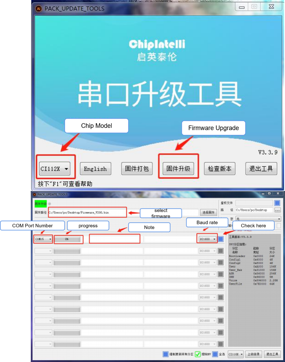
- Turn on the power switch. When you see the LED light up on the development board, it indicates power is on and the firmware download will begin.
- After the firmware download is complete, power cycle the board. Upon startup, you will hear “Welcome to Smart Home Assistant, you can wake me up by saying ‘Hello Jenny’.” When you say “Hello Jenny,” the board will respond with “I am here,” indicating the standard firmware has been successfully installed and the development board is working properly.
- If you encounter any issues, please contact our technical support for assistance.
Application Notes
For information on how to program and debug this development board, please refer to the document: ☞《CI13LC Chip SDK》. This document contains detailed instructions for programming and debugging procedures specific to this development board.