CI1301&CI1302&CI1303 Development Kit
Overview
The CI1301&CI1302&CI1303 development board consists of a module board (CI-D03GS02S/CI-D02GS02S/CI-D01GS02S, ☞CI-D0XGS02S), a universal baseboard (CI-B02-MB, ☞CI-B02-MB), a microphone, and a speaker. The CI1301&CI1302&CI1303 development kit includes a CI1303 development board, a serial debugging tool, an audio acquisition board, a USB cable, and DuPont wires. The development board comes with standard firmware pre-installed and can be woken up using the wake word “Hello Jenny”. The serial debugging tool included in the kit can also be used to download new firmware. This document provides a progressive introduction from basic to advanced topics, covering the composition and concepts of the development board and kit, differences between CI1301/CI1302/CI1303 development board models, an introduction to the universal baseboard, features of the development kit, and application examples. First, let’s briefly explain the composition and concepts of the development board and kit.
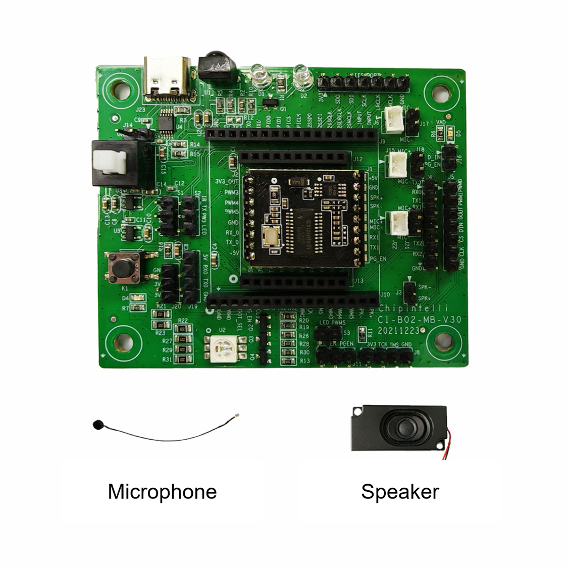
The composition of the CI1301&CI1302&CI1303 development board is as follows:
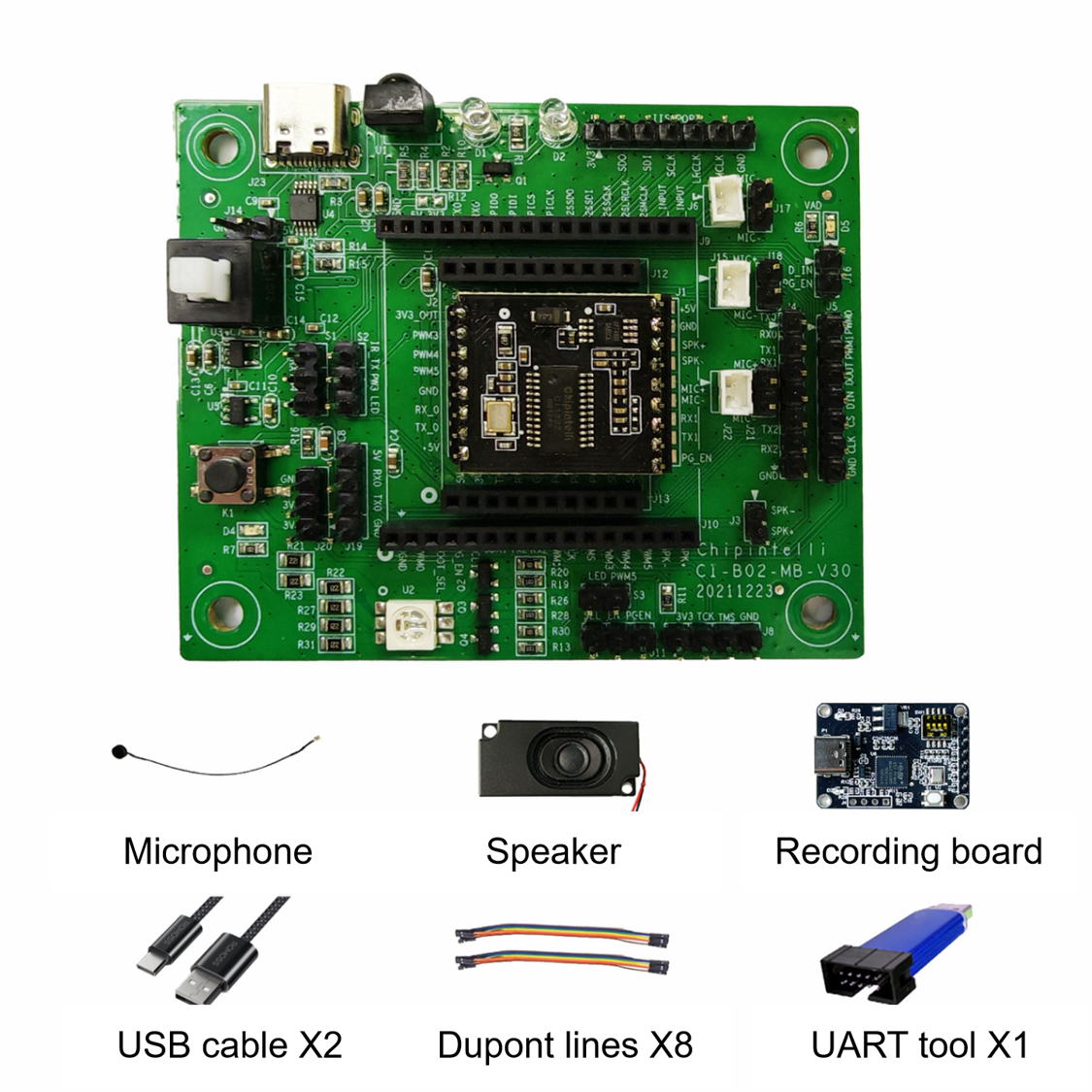
The composition of the CI1301&CI1302&CI1303 development kit is as follows:
Development Board Model Differences
The three models of CI1301&CI1302&CI1303 development boards differ in their main chips, which are CI1301, CI1302, and CI1303. The specific differences are shown in the following table:
| No. | Development Board Model | Main Chip Model | FLASH Size | Description |
|---|---|---|---|---|
| 1 | CI1303 Development Board | CI1303 | 4MB | Supports larger models, more command words Supports more algorithms |
| 2 | CI1302 Development Board | CI1302 | 2MB | Supports medium models, more command words |
| 3 | CI1301 Development Board | CI1301 | 1MB | Supports smaller models, moderate number of command words |
Universal Baseboard Introduction
The Chipintelli Universal Baseboard CI-B02-MB (hereinafter referred to as the baseboard) can be paired with CI110X series SMT modules, CI112X series SMT modules, CI130X series SMT modules, and CI13LCX series SMT modules to form different series of evaluation kits. It enables basic voice recognition and announcement function demonstrations, interface expansion applications, and user firmware development verification. Below is a detailed introduction to the universal baseboard.
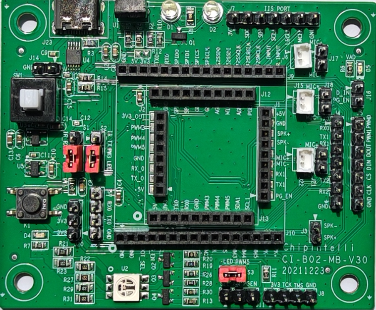
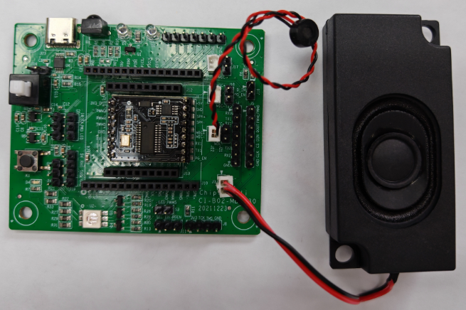
The appearance of the baseboard is as follows:
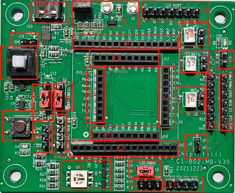
The baseboard features rich interfaces. The specific interface functions, signal names, and descriptions are shown in the following table.
Functional definitions of each interface on the baseboard are as follows:
| Ref. | Position | Function & Definition | Description | Notes |
|---|---|---|---|---|
| J23 | 1 | TYPE-C Port | TYPE-C Interface 5V Power Input Firmware Download Port |
Note: This interface serves as both power supply and data download port |
| J14 | 2 | 5V GND |
5V (5V Power Supply) GND (Ground) |
2PIN-2.54 Header 5V Power Input |
| SW1 | 3 | Baseboard Power Button | Press to turn off Release to turn on |
Check if power indicator is lit |
| K1 | 4 | Expansion Button | Trigger function | Not in use |
| J20 | 5 | 3.3V, 3.3V, GND | 3PIN-2.54 3.3V Power Output |
Max output 50mA |
| J19 | 6 | 5V RX0 TX0 GND |
5V (5V Power Input) RX0 (UART0 Receive) TX0 (UART0 Transmit) GND (Ground) |
4PIN-2.54 Alternate firmware download port |
| S1 | 7 | IR_RX PWM4 LED |
PWM4 shorted to IR_RX Selects IR receive function PWM4 shorted to LED Selects green LED control function |
3PIN-2.54 PWM4 function selection |
| S2 | 8 | IR_RX PWM3 LED |
PWM3 shorted to IR_TX Selects IR transmit function PWM3 shorted to LED Selects blue LED control function |
3PIN-2.54 PWM3 function selection |
| S3 | 9 | PWM5 LED |
PWM5 shorted to LED Selects red LED control function |
2PIN-2.54 PWM5 function selection |
| J11 | 10 | SEL EN PGEN |
EN shorted to SEL Power on enters JTAG debug mode EN shorted to PGEN Power on enters upgrade mode |
Generally use upgrade mode for firmware download Connect jumper cap between EN and PGEN |
| J8 | 11 | 3.3V TCK TMS GND |
3.3V (max 50mA output) TCK (JTAG_TCK) TMS (JTAG_TCKTMS) GND (Ground) |
4PIN-2.54 JTAG debug pins, not available for CI130X/CI13LCX series |
| J3 | 12 | SPK- SPK+ |
Connect to 8Ω/2W or 4Ω/3W speaker | 2PIN-2.54 Speaker interface, no polarity |
| J4 | 13 | TX0 RX0 TX1 RX1 TX2 RX2 GND |
TX0 (UART0 Transmit) RX0 (UART0 Receive) TX1 (UART1 Transmit) RX1 (UART1 Receive) TX2 (UART2 Transmit) RX2 (UART2 Receive) GND (Ground) |
Can connect to UART0, UART1 UART2 not available for voice module UART0 is connected to UART0 of J19 |
| J5 | 14 | PWM0 PWM1 DOUT DIN CS CLK GND |
PWM0 (PWM0 Interface) PWM1 (PWM1 Interface) DOUT (Expanded SPI) DIN (Expanded SPI) CS (Expanded SPI) CLK (Expanded SPI) GND (Ground) |
7PIN-2.54 Expansion function port |
| J16 | 15 | D-IN PG_EN |
D-IN (Expanded SPI Input) PG_EN (Upgrade Enable) |
PG_EN has same function as PGEN pin on J11 |
| J21 J22 |
16 | MIC+ MIC- |
MIC+ (Microphone Positive) MIC- (Microphone Negative) |
Can connect to 2.54mm or 1.25mm pitch microphones, compatible with C22GS02S\D02GS02S\D03GS02S\F24GS01S |
| J15 J18 |
17 | MIC+ MIC- |
MIC+ (Microphone Positive) MIC- (Microphone Negative) |
Can connect to 2.54mm or 1.25mm pitch microphones, compatible with B02GS04S\B03GS04S modules |
| J6 J17 |
18 | MIC+ MIC- |
MIC+ (Microphone Positive) MIC- (Microphone Negative) |
Can connect to 2.54mm or 1.25mm pitch microphones, no compatible modules currently |
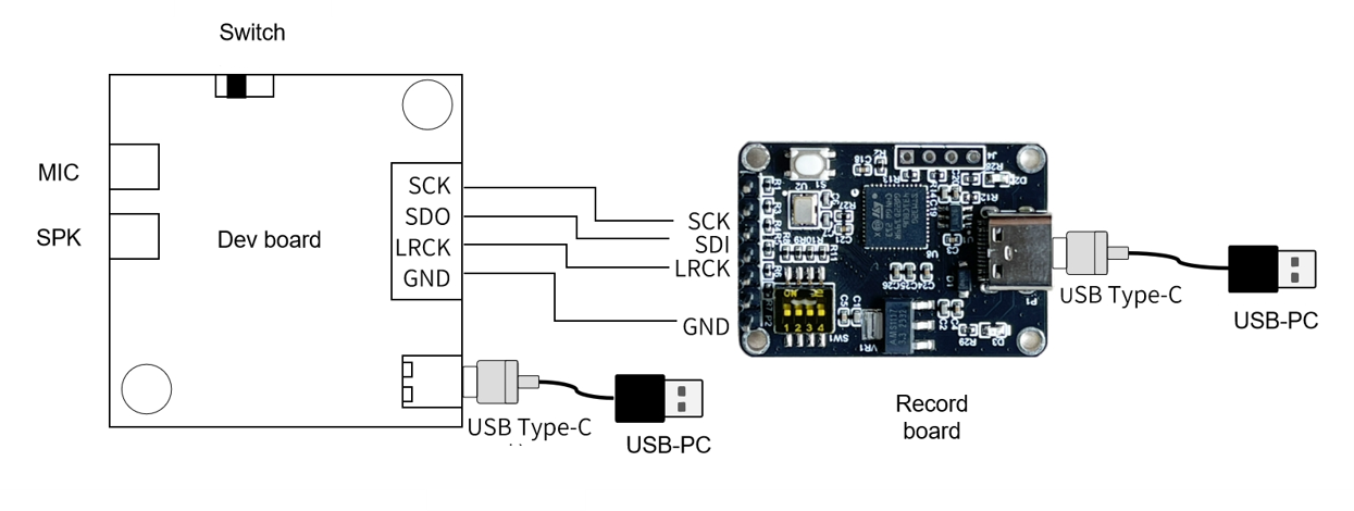
| J7 | 19 | 3.3V SDO SDI SCLK LRCK MCLK GND |
3.3V (Power Output) SDO (IIS_SDO) SDI (IIS_SDI) SCLK (IIS_SCLK) LRCK (IIS_LRCK) MCLK (IIS_MCLK) GND (Ground) |
Supports connection to audio acquisition board for audio recording |
| J1 D1 D2 |
20 | IR_RX IR_TX |
IR Transmit IR Receive |
To use this function, short-circuit interfaces 7 and 8 for configuration |
| J12 J13 |
21 | Module Interface | Connect to voice module | CI-B02GS04S CI-B03GS04S |
| J9 J10 |
22 | Module Interface | Connect to voice module | No compatible voice modules currently |
| J1 J2 |
23 | Module Interface | Connect to voice module | CI-C22GS02S CI-D02GS02S CI-D03GS02S CI-D01GS02S CI-F24GS01S |
| U2 | 24 | RGB LED | Controlled by PWM3\PWM4\PWM5 | To use this function, short-circuit interfaces 7, 8, and 9 for configuration |
For more detailed information about the baseboard interfaces and their applications, please refer to the baseboard schematic file below:
Development Kit Features
The development kit consists of a development board, serial debugging tool, audio acquisition board, USB cable, and DuPont wires. The microphone is mainly used for voice input, the speaker is mainly used for audio output, the serial debugging tool is mainly used for firmware download and debug information printing, and the audio acquisition board is mainly used for audio data collection and analysis. The following describes how to connect each component to the development board.
The microphone connector on the CI1301&CI1302&CI1303 development board is J22. The microphone has polarity, and the connector is keyed. The speaker connector is J3, which has no polarity. The connection method for the development board microphone and speaker is shown in the figure below:
There are two ways to download firmware to the development board. The hardware connection diagrams for both methods are as follows:
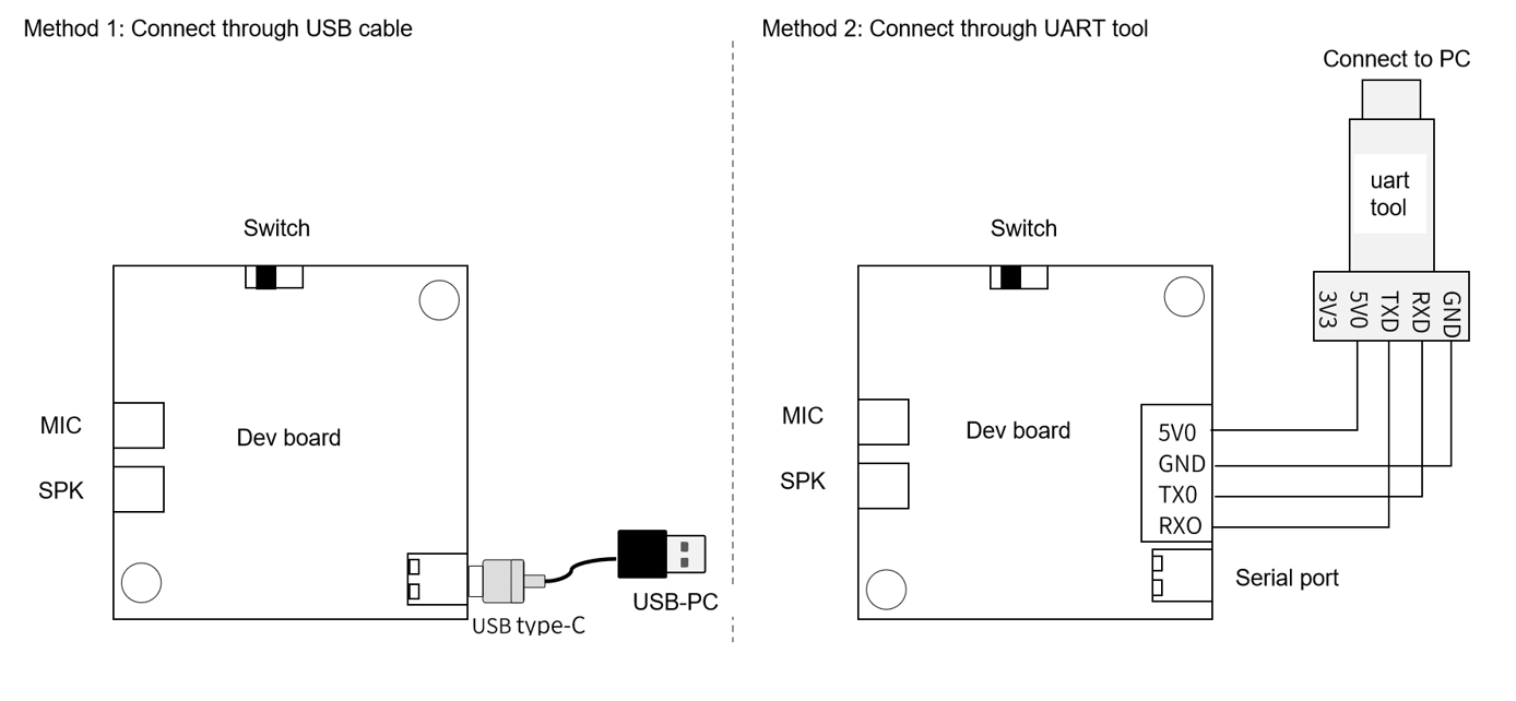
The hardware connection diagram for development board communication and LOG printing is as follows:
Application Example
The following example demonstrates how to use this development kit by programming a module board with standard firmware, waking it up with voice, controlling it with voice commands, and having the development kit provide voice feedback.
Note: When users purchase our CI-D03GS02S\CI-D02GS02S\CI-D01GS02S module samples, they will come with a basic firmware that provides feedback through the speaker when command words are recognized.
Preparation
To complete this example, prepare the materials listed in Table 2. For CI1301 chip development, you can choose the CI-D02GS02S module. The firmware size should be less than 1MB.
| Name | Description | Quantity | Purchase Method |
|---|---|---|---|
| CI-D03GS02S CI-D02GS02S |
Voice Module Board | 1 | ☞Sample Purchase |
| CI-B02-MB | Module Baseboard | 1 | ☞Sample Purchase |
| Microphone | Sound Pickup | 1 | ☞Sample Purchase |
| Speaker | Sound Playback | 1 | ☞Sample Purchase |
| Full-featured TYPE-C Cable | Connect to Computer for Firmware Download & Power |
1 | Mobile phone data cable or purchase separately |
Example Connection Diagram
A physical connection diagram for using the development kit is shown below:
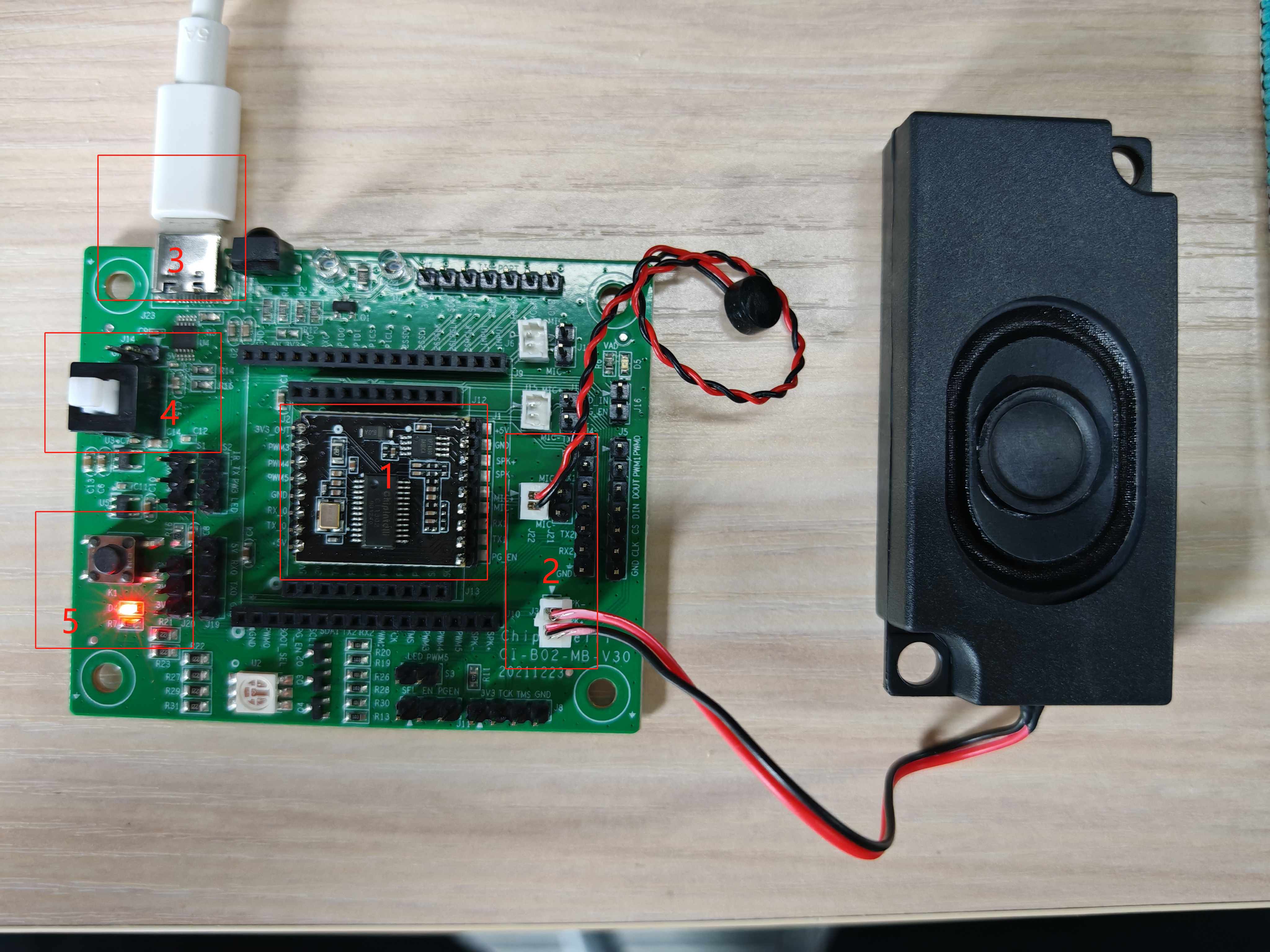
Connection method:
- Insert the CI-D0XGS02S module board into position 1 marked by the red box in the figure above (already installed when shipped);
- Connect the microphone to the socket marked as position 2 in the red box above (note: align MIC+ to MIC+ and MIC- to MIC-), with the black wire facing the speaker socket;
- Connect the speaker to the socket marked as position 2 in the red box above (no polarity).
Operation Steps
After connecting the development kit as shown in the connection diagram above, you can operate it according to the following steps:
- Connect one end of the TYPE-C cable to the USB port of your computer or a 5V charger, and the other end to the power interface of the baseboard (position 3 marked by the red box in the connection diagram);
- Press the power button (position 4 marked by the red box in the connection diagram). When the red light on the baseboard lights up, it means the power is on (position 5 marked by the red box);
- After powering on, you will hear “Welcome to use smart fan, please use ‘hello Jenny’ to wake me up”. When you say “hello Jenny”, you will hear the development board respond with “Hello”, indicating that the module, power supply, microphone, and speaker are connected correctly;
- If there are any abnormalities, please refer to the “Frequently Asked Questions” section at the end of this document. If problems persist, please contact our technical support.
Standard Module Command Words and Corresponding Voice Prompts
Our standard module comes with standard firmware pre-installed. To use it, first say the wake word “hello Jenny”. After hearing the response “Hello”, you can say other command words. When you hear “Thank you for using”, it means the module has exited the wake state and you need to say “hello Jenny” to wake it up again.
The following table lists the command words corresponding to our standard firmware: Note: Some command words may be added or removed as needed without prior notice.

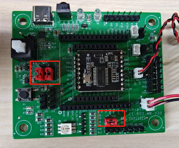
Controlling the Tri-color LED on the Baseboard
This development kit can control the tri-color LED on the baseboard through voice commands. This feature is available on CI-D01GS02S, CI-D02GS02S, and CI-D03GS02S modules.
After connecting the hardware according to the above connection method, you can perform the following steps:
- Connect the microphone and speaker properly;
- Use jumper caps to connect the control pins of the tri-color LED at the two positions marked with red boxes in the figure below.
After the hardware connection, you can write code to implement the control. The SDK is required for writing code, as explained below:
- For CI-D02GS02S or CI-D03GS02S modules, please download the CI130X chip SDK: ☞CI130X Chip SDK
For software development related information, please click ☞CI130X Chip SDK
After the firmware development is completed, Firmware Update is required. Please refer to the following document for specific operations:
☞Programming and Debugging Methods
Note: When viewing the “Programming and Debugging Methods” document, please pay attention to the following instructions:
- Since the baseboard has built-in USB-to-serial port functionality, you can start from the second paragraph of section 1.1 in the document;
- The PG_EN pin refers to the red box marked as 10 in the ‘Baseboard Interface and Application Instructions’ section of the document.
After the module programming is completed, power cycle the device. Confirm that the power-on announcement is normal, the wake-up function works, and it can respond to command words and control the LED. This completes the development.
Application Notes
- The power supply voltage specification for the baseboard is 5V±5%, and the rated current of the power supply must be greater than 500mA. Otherwise, insufficient power supply to the voice module may occur when the speaker is working, causing abnormal function of the voice module;
- The baseboard and voice module should be stored and operated within a temperature range of 0-85°C;
- All communication interfaces of the baseboard kit operate at 3.3V level. When connecting to external devices, ensure the external device’s communication level is also 3.3V, otherwise use a level conversion circuit;
- For any questions about the baseboard and voice module, or for special application/development requirements, please consult our technical support team.
Frequently Asked Questions
| No. | Symptom | Troubleshooting Steps |
|---|---|---|
| 1 | No Sound Output | 1. Check if the speaker is connected to the correct port, refer to the connection diagram above; 2. Check if the power indicator is lit. If not, verify if the power supply is providing normal 5V; 3. Check if the power button is in the released (on) position. |
| 2 | No Response to “Hello Jenny” | 1. Check if the microphone is connected to the correct terminal, refer to connection diagram 8 above; 2. Check if the speaker is connected to the correct terminal, refer to connection diagram 8 above; 3. Try to use standard Mandarin pronunciation; 4. Restart the device to see if it works normally. |
| 3 | Computer Cannot Detect Serial Port | 1. Check if the power indicator is lit. If not, verify if the power supply is providing normal 5V; 2. Check if the power button is in the released (on) position; 3. Try flipping the TYPE-C cable connected to the baseboard. |