SDK Quick Start
1. Overview
This document serves as a quick start guide for the CI13LC series chip software development kit (SDK), designed to assist developers in rapid code development.
2. User Guide
2.1. Development Environment
The following software and hardware are required for development:
- IDE Development Software
- CI13LC Series Chip SDK
- Serial Port Programmning Tool
2.1.1. IDE Development Software
All applications in the SDK can be compiled and used with the general-purpose VSCode tool. Users can refer to the document ☞《Installation and use of compiler software》 for installation, or download it from the ☞Chipintelli AI Speech Development Platform resource library.
2.1.2. CI13LC Series Chip SDK Package
The SDK includes example projects, documentation, and necessary tools. Users can download it from the ☞Chipintelli AI Speech Development Platform resource library.
2.1.3. Serial Port Programmning Tool
We provide the PACK_UPDATE_TOOL.exe serial port programming tool for the CI13LC series chips, used for firmware flashing and upgrading. For details on the serial port upgrade process, refer to Chapter 4 - flashing.
2.2. Development Board Introduction
This section introduces the hardware using the CI13LC series chip standard development board CI-F32XGT01D as an example. Users can purchase this development board from ☞Sample Purchase.
2.2.1. Development Board Diagram
Model: CI-F32XGT01D (Main Chip CI13322).
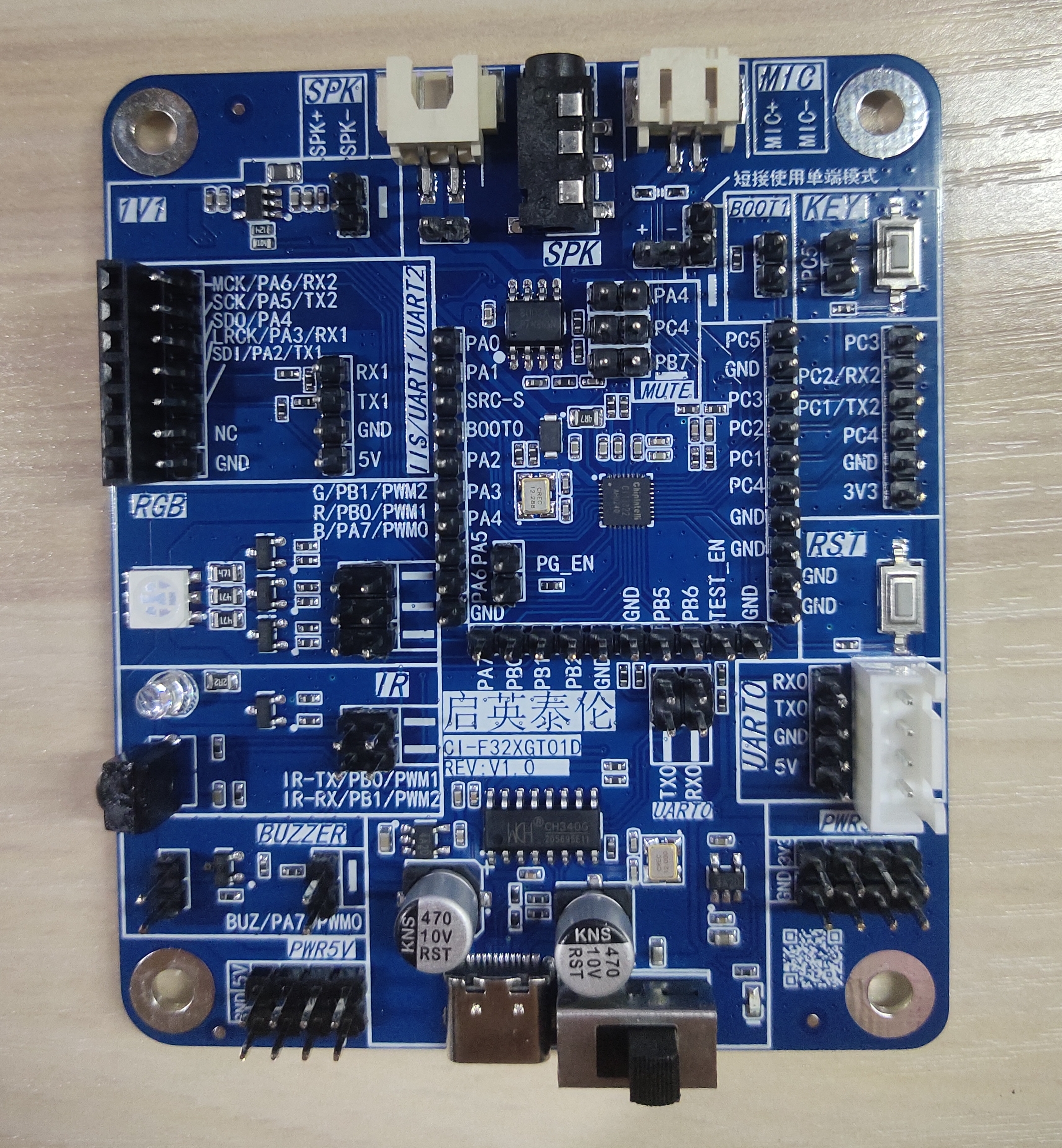
2.2.2. Development Board Introduction
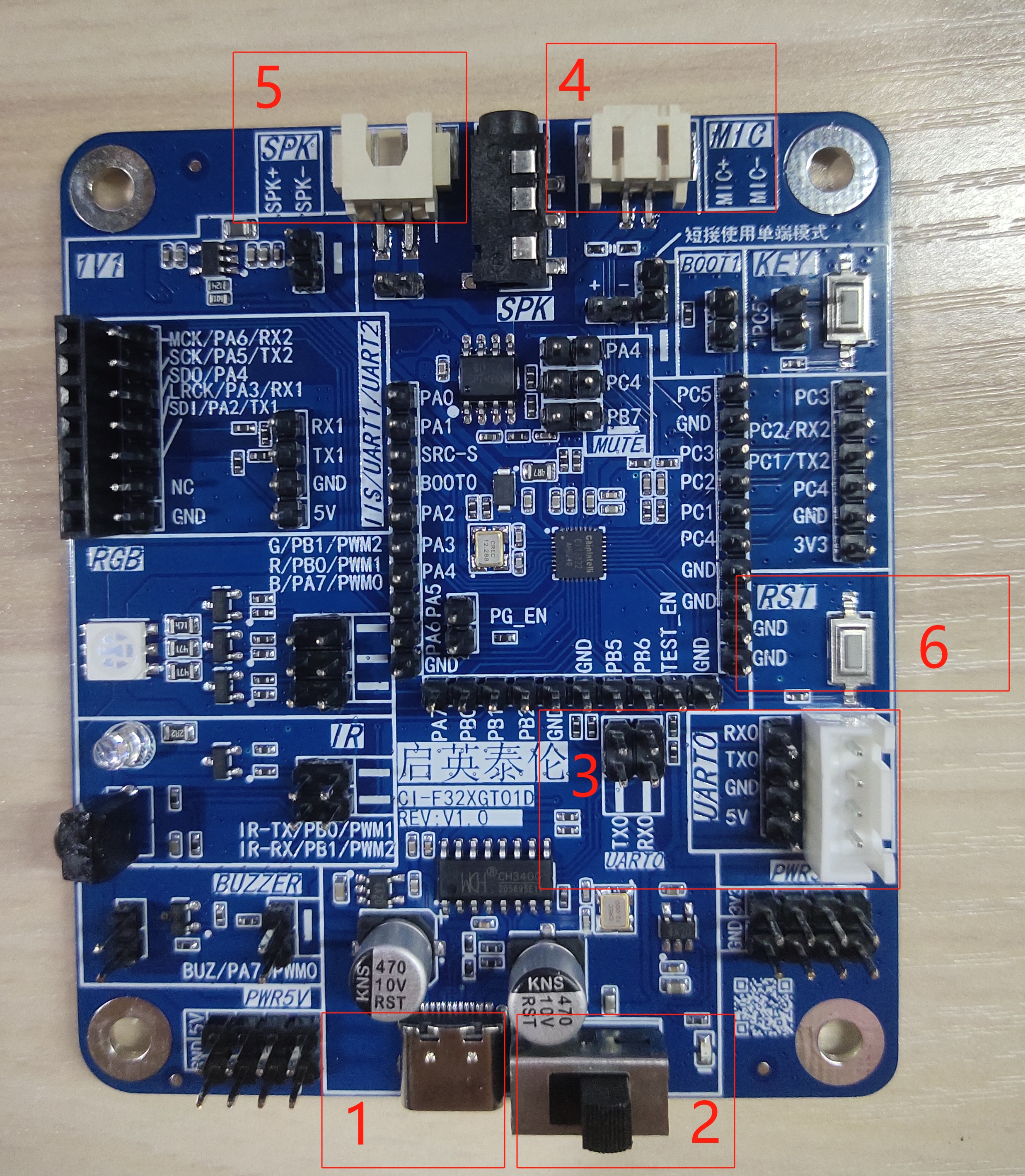
- The hardware diagram of the CI-F32XGT01D development board is as follows:
-
1: TYPE-C Data Interface, can be used for power connection and serial port upgrade.
-
2: 5V Power Input, GND, and Power Button.
-
3: UART0_TX and UART0_RX for Firmware Update. These pins need to be shorted when using TYPE-C for upgrade.
-
4: Microphone Base.
-
5: Speaker Base.
-
6: Reset Button, needs to be pressed during the upgrade process to start the upgrade.
3. Application
Currently, one set of SDK is provided for the CI13LC series chips: CI13LC_SDK (Offline Voice Recognition SDK).
3.1. SDK Overall Architecture Introduction
| File Name | Description |
|---|---|
| components | Directory for components including player, ASR recognition, buttons, sensors, FreeRTOS operating system, etc. |
| driver | Directory includes CI13LC series chip underlying drivers and board support configuration |
| libs | Directory includes library files |
| projects | Directory includes example projects |
| startup | Directory includes CI13LC series chip startup code |
| system | Directory includes system-related code, interrupt handlers, and platform configurations |
| tools | Tools directory, mainly for merging and packaging upgrade tools |
3.2. CI13LC_SDK Example Project Introduction
To help developers quickly create applications, example projects have been included in CI13LC_SDK. By studying these examples, developers can easily familiarize themselves with the SDK.
Example project path: CI13LC_SDK\projects\
| Project File | Description |
|---|---|
| offline_asr_pro_sample | CI13LC Series Chip Offline Recognition Project |
4. Flashing
4.1. Partition Images
The CI13LC series chip application requires 5 images: asr.bin, dnn.bin, user_code.bin, user_file.bin, and voice.bin
- asr.bin: Voice model;
- dnn.bin: Acoustic model;
- user_code.bin: Application developed by the developer, generated through VSCode compilation;
- user_file.bin: Command word list defined by the developer and other bin files;
- voice.bin: Voice prompts.
4.2. Make Partition Images
- Path: SDK\projects\offline_asr_pro_sample\firmware\
- Name: make_partition_bin.bat
- Function: After running this script, it will automatically generate asr.bin, dnn.bin, user_file.bin, and
voice.binfiles in the firmware\asr, dnn, user_file, and voice directories respectively.
4.3. Flashing Method
Use the PACK_UPDATE_TOOL.exe serial port programming tool to update the firmware. The following uses the offline_asr_pro_sample project as an example for flashing.
Step 1: Serial Port Flashing Hardware Connection
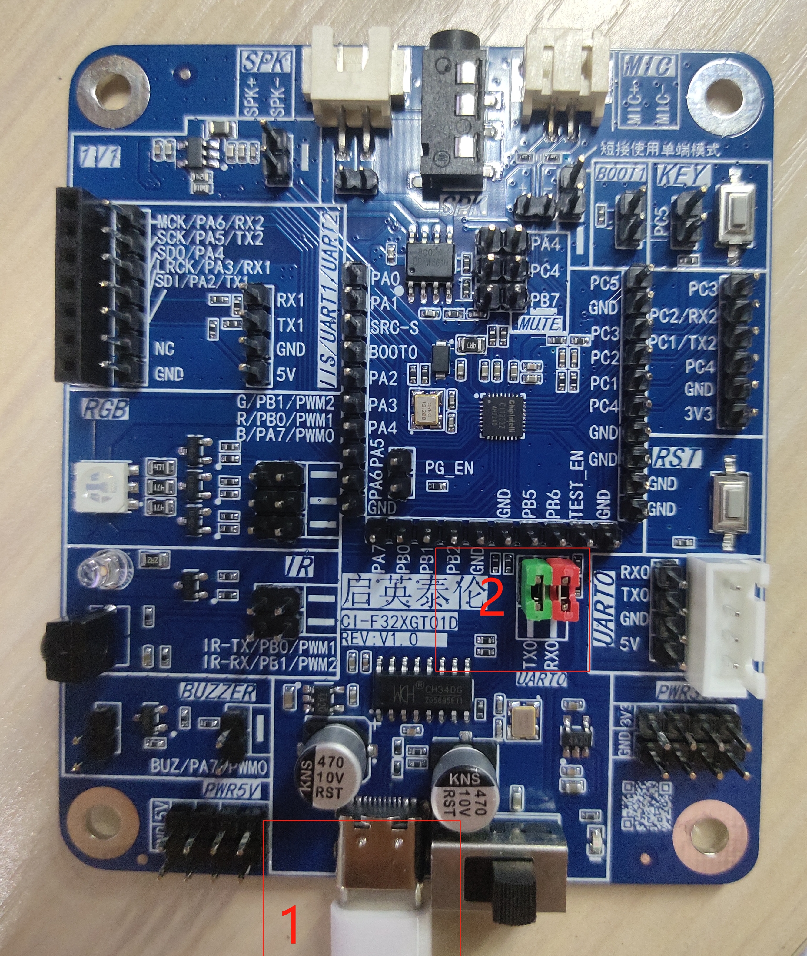
(1) Using TYPE-C upgrade hardware connection method:
- 1: TYPE-C cable, connect to PC
- 2: Short TX0 and RX0
(2) Using USB-to-Serial tool upgrade hardware connection method:

- 1: Power (5V/GND)
- 2: TX0 and RX0 connected to RXD and TXD of USB-to-Serial tool
- 3: USB-to-Serial tool, connect to PC
Step 2: Compile the Code to Generate user_code.bin File
(1) For compilation method, please refer to the document ☞《Installation and use of compiler software》
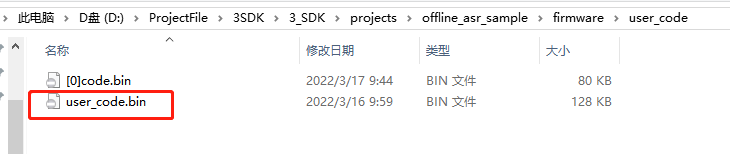
(2) After compilation is complete, the application code user_code.bin will be generated in SDK\projects\offline_asr_pro_sample\firmware\user_code, as shown in Figure 4-3 below:
Step 3: Generate the Other 4 Required bin Files
Method 1: Direct Synthesis in Compilation Software
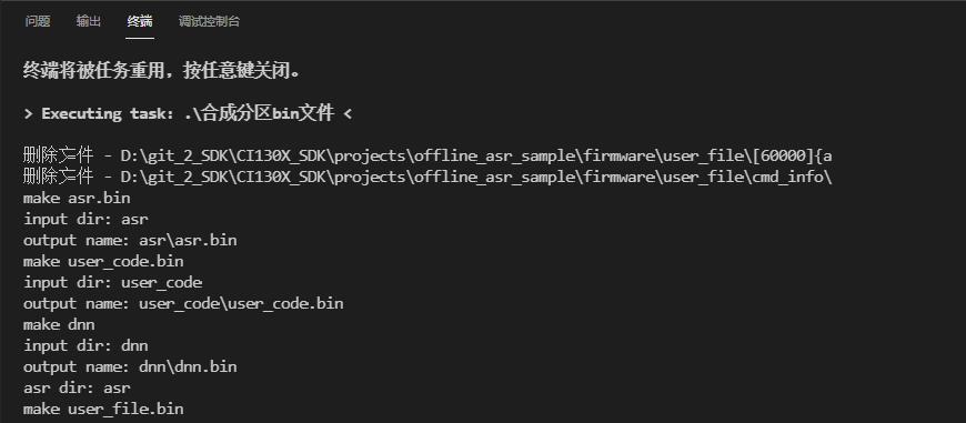
(1) As shown in the steps below, run (make_partition_bin.bat):
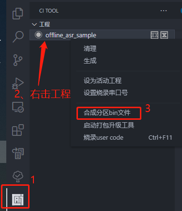
(2) The compilation software terminal synthesis results are as follows:
Method 2: Double-click to Run the Script (make_partition_bin.bat)
(1) Go to SDK\projects\offline_asr_pro_sample\firmware\, as shown in Figure 4-6 below:
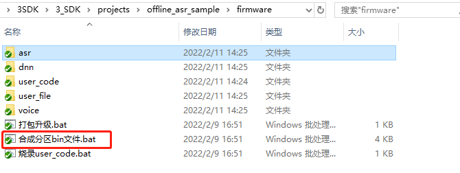
(2) Double-click to open make_partition_bin.bat. The running interface is shown in Figure 4-7. Wait for the software to complete and exit automatically. After running the script, asr.bin, dnn.bin, user_file.bin, and voice.bin files will be automatically generated in the SDK\projects\offline_asr_pro_sample\firmware\asr, dnn, user_file, and voice directories respectively.
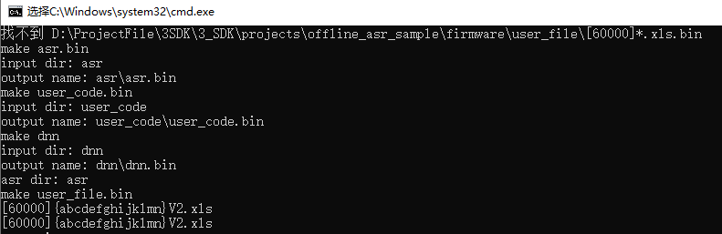
Note
- After 10 seconds of processing, cmd.exe will exit automatically. If it doesn’t exit automatically, the
*.binfile generation failed. Please check if the files or filenames in the asr, dnn, user_file, and voice directories are correct.
Step 4: Package the 5 bin Files into One bin File
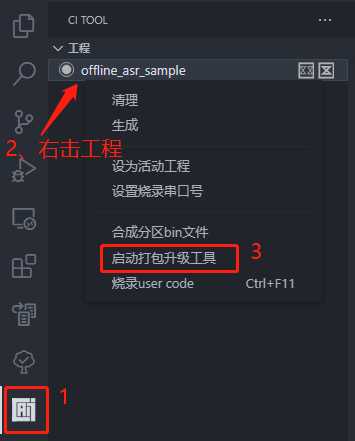
Method 1: As shown in the figure below, start the pack and updatetool PACK_UPDATE_TOOL.exe in the VSCode compilation environment
Method 2: Go to SDK\projects\offline_asr_pro_sample\firmware\, as shown in Figure 4-6, double-click (打包升级.bat) to open PACK_UPDATE_TOOL.exe
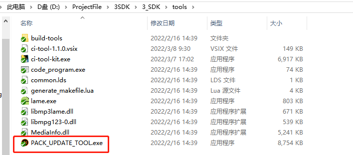
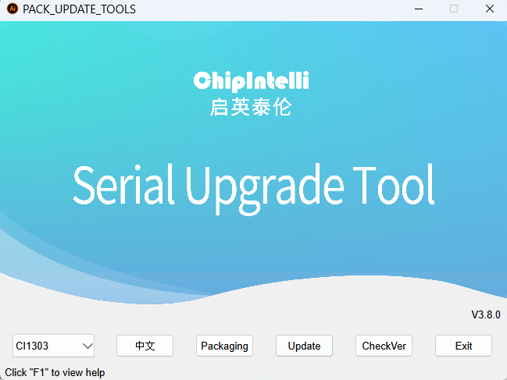
Method 3: Go to SDK\tools\, open PACK_UPDATE_TOOL.exe. The interface is shown in Figure 4-9 below:
When opening the software for the first time, a prompt box will pop up as shown in Figure 4-10 below. Here, you need to select the CI13LC series chip.
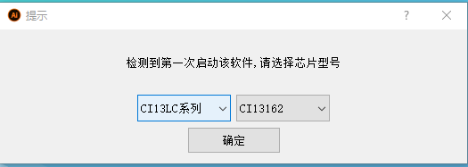
- CI13LC Series: Current chip is from the CI13LC series;
- CI13162: Current model is CI13162 from the CI13LC series;
- English: Currently displayed in Chinese, click to switch to English display;
- Firmware Packaging: Switch to firmware packaging interface;
- Firmware Update: Switch to Firmware Update interface;
- Press “F1” for help: More instructions on using the upgrade tool.
Click the (Firmware Packaging) button on the main interface of the serial port programming tool. The interface is shown in Figure 4-12 below:
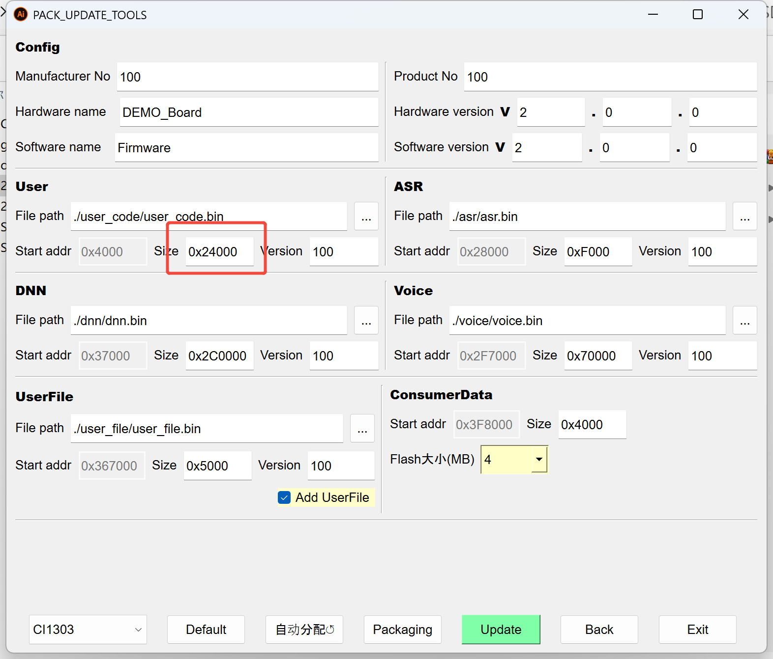
Click the (Auto Allocate) button to automatically allocate the start address and reserved size based on the file sizes of user_code.bin, asr.bin, dnn.bin, etc. If you want to reserve extra space for a certain partition, manually modify the reserved size, then click the (Package Firmware) button.
Note
- The reserved size should be configured in multiples of 0x1000.
- Different chips have different flash sizes. For example, the last digit of CI13161 indicates 1M flash, CI13160 indicates 0.5M flash, and CI13162 indicates 2M flash.
- It is recommended to switch to the corresponding chip model for firmware packaging. The FLASH size on the interface can only change with the chip model and cannot be modified manually.
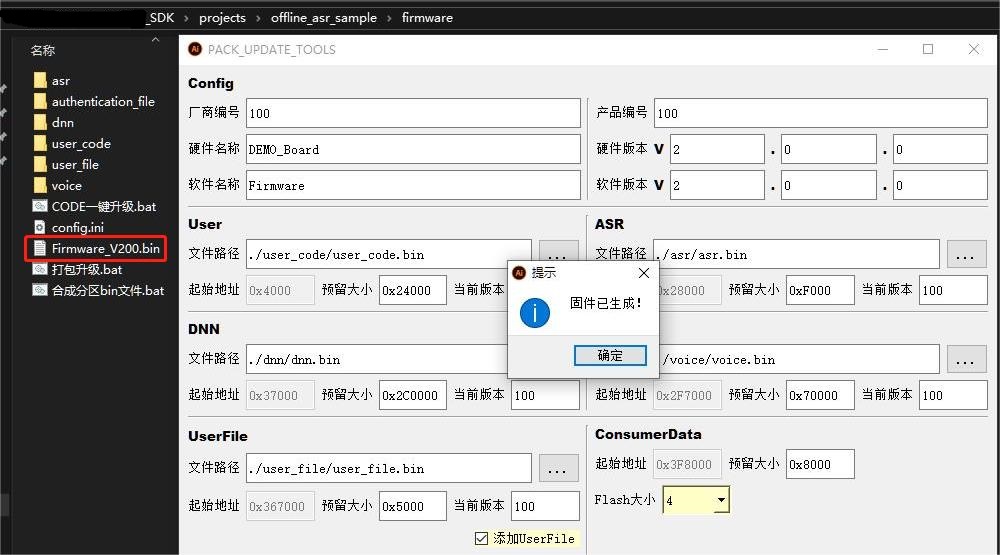
Click the (Package Firmware) button. A window will appear indicating that the firmware has been generated, which means the firmware creation is complete.
After clicking OK, a *.bin file will be generated in the SDK\projects\offline_asr_pro_sample\firmware directory. The name of the *.bin file consists of the software name and software version from the packaging interface. For example, as shown in Figure 4-13, Firmware_V200.bin:
Step 5: Update Firmware
After completing the above steps, it is recommended to confirm the following:
- Ensure the hardware connection is correct (refer to Step 1 for details);
- Ensure the TYPE-C cable or USB-to-Serial tool is connected to the PC and the PC can recognize the COM port;
- Ensure the firmware is generated correctly;
- Ensure the microphone and speaker are correctly connected to the development board.
Click the Firmware Update button on the interface shown in Figure 4-10 or 4-11. The interface is shown in Figure 4-14 below:
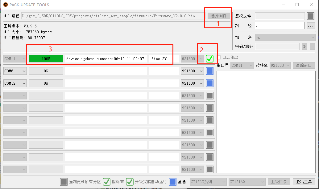
- 1: Select the firmware generated in Step 4 or the firmware provided by our company;
- 2: Select the correct COM port;
- 3: Reset the development board (either by pressing the reset button or by power cycling). The development board will automatically start the upgrade. After the upgrade is complete, it will display “update successful”. “Size:2M” indicates the current chip’s flash size.
Tip
For more information on firmware development, please visit ☞《Command Word and Firmware Development Guide》 page, or press “F1” on the home page shown in Figure 4-10 to view help.
Step 6: Verify Firmware
After the flashing is complete, or after restarting the development board, the offline_asr_pro_sample project will have voice prompts after startup. After the prompts complete, say the wake word “Smart Agent” and it will respond with “I am here”, indicating a successful upgrade.
If there is no voice prompt, please refer to the following (Chapter 5 - Debugging) to find the specific reason.
5. Debugging
There is one way to debug the application:
- Use the log mechanism to track code execution and data.
5.1. Log Mechanism
Track the execution of the application by printing logs through the serial port.
5.1.1. Log Output Pin Configuration
The UART0_TX pin is the default output pin for Log UART (the log function can also be reconfigured to other pins). If configuring another serial port as the log output, configure the macro CONFIG_CI_LOG_UART. Modify or add the macro definition in user_config.h as shown in Figure 5-1:
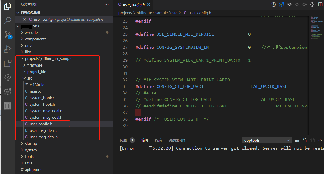
It is recommended that users configure in the user_config.h file in the project directory and not directly modify the macro definitions in sdk_default_config.h.
5.1.2. Log Serial Debug Tool Configuration
The PC serial debug tool configuration is as follows. The default baud rate for UART0 printing in the SDK is 921600:
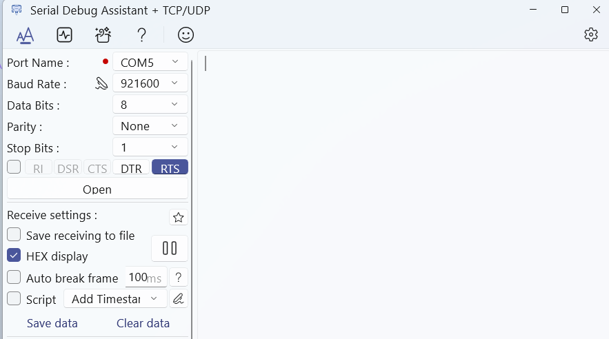
Note
Since the serial port output contains Chinese, it is recommended to use a serial debug tool that supports UTF-8 fonts.
Recommended serial debug tool: SecureCRT. For more information about SecureCRT, please visit: ☞https://www.vandyke.com/products/securecrt/
5.1.3. Log Printing General Interface
General log printing interface:
mprintf(fmt, args…), usage is the same as printf.
5.1.4. Log Printing API
For user convenience in debugging, the SDK supports the following interfaces:
Table 5-1 Printing API
| Debug API | Function |
|---|---|
| ci_logverbose(comlevel, message, args…) | Log Print – Verbose |
| ci_logdebug(comlevel, message, args…) | Log Print – Debug |
| ci_loginfo(comlevel, message, args…) | Log Print – Info |
| ci_logwarn(comlevel, message, args…) | Log Print – Warning |
| ci_logerr(comlevel, message, args…) | Log Print – Error |
| ci_logassert(comlevel, message, args…) | Log Print – Assert |
Debug levels, indicating the level of logs to be printed. Seven categories are defined:
Table 5-2 Debug Levels
| Debug Level | Usage Scenario |
|---|---|
| #define CI_LOG_VERBOSE | Print all |
| #define CI_LOG_DEBUG | Debug, Info, Warning, Error, Assert |
| #define CI_LOG_INFO | Info, Warning, Error, Assert |
| #define CI_LOG_WARN | Warning, Error, Assert |
| #define CI_LOG_ERROR | Error, Assert |
| #define CI_LOG_ASSERT | Assert only |
| #define CI_LOG_NONE | No printing |
Note
To use the interfaces in Table 5-1, CONFIG_CI_LOG_EN must be defined as 1.
5.1.5. Log Print Length Configuration
#define UART_LOG_BUFF_SIZE 512
The default print length is 512 bytes. The print length can be modified by configuring the UART_LOG_BUFF_SIZE macro.