Universal Asynchronous Receiver/Transmitter (UART)
1. Introduction
UART (Universal Asynchronous Receiver/Transmitter) is a general-purpose serial data bus used for asynchronous communication, enabling full-duplex transmission and reception.
2. Timing
2.1. Basic Introduction
- UART works by transmitting binary data bit by bit. In the UART communication protocol, a high level on the signal line represents ‘1’ and a low level represents ‘0’.
- Simple hardware connection requiring only 3 lines: TX, RX, and GND.
- TX (Transmit Data, connect to the RX of the target device)
- RX (Receive Data, connect to the TX of the target device)
- Idle bit (When the bus is idle, the signal line state is ‘1’ or high level)
- Start bit (A low level ‘0’ is sent first to indicate the start of character transmission)
- Data bits (After the start bit, the data to be transmitted follows, usually 8 bits. The least significant bit is sent first, and the most significant bit is sent last)
- Parity bit (After the data bits, parity checking is performed)
- Stop bit (End-of-data marker, can be 1, 1.5, or 2 bits of high level)
- Baud rate (The time to transmit one bit is (1/baud rate) seconds)
2.2. Timing Diagram Analysis
- (1) Timing diagram for transmitting 1 byte, including start bit, 8 data bits, and stop bit.
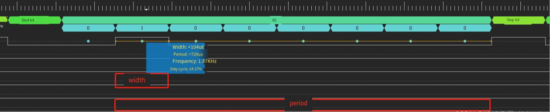
- (2) Baud rate calculation: Find the width of 1 bit of data. For example, in the figure below, the time is 104 μs.
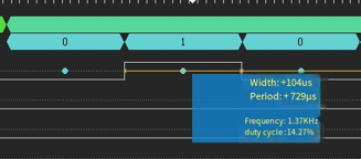
- Calculation: 1/baud rate = 104 μs = 1.04e-4 s, resulting in a baud rate of approximately 9600.
3. API
| Function Name | Description |
|---|---|
| UARTPollingConfig | UART polling mode initialization |
| UARTInterruptConfig | UART interrupt mode initialization |
| UARTDMAConfig | UART DMA mode initialization |
| UART_IntMaskConfig | UART interrupt mask configuration |
| UART_IntClear | UART interrupt flag clear |
| UartPollingReceiveData | Polling mode receive one byte |
| UartPollingSenddata | Polling mode send one byte |
4. Examples
1) The following code configures UART0 in polling mode, sends and receives data, and verifies the data after transmission:
#include "ci13lc_uart.h"
void main(void)
{
    // Initialize send/receive data arrays
    int i;
    unsigned char buf_send[32] = {0x0};
    unsigned char buf_recv[32] = {0x0};
    for(i = 0; i < 32; i++)
    {
        buf_send[i] = i;
    }
    // Initialize UART0 (polling mode), baud rate 115200
    UARTPollingConfig(UART0, UART_BaudRate115200);
    // Send data: one byte at a time
    for(i = 0; i < 32; i++)
    {
        UartPollingSenddata(UART0, buf_send[i]);
    }
    // Receive data: one byte at a time
    for(i = 0; i < 32; i++)
    {
        buf_recv[i] = UartPollingReceiveData(UART0);
    }
    // Compare sent and received data
    for(i = 0; i < 32; i++)
    {
        if(buf_send[i] != buf_recv[i])
        {
            mprintf("Comparison of the Data Fail\n");
            while(1);
        }
    }
    mprintf("Comparison of the Data Successful\n");
    while(1);
}
2) The following code configures UART0 in interrupt mode, sends data using polling, receives data using interrupts, and verifies the data after transmission:
#include "ci13lc_uart.h"
unsigned char buf_send[32] = {0x0};
unsigned char buf_recv[32] = {0x0};

void pad_config_for_uart(UART_TypeDef *UARTx)
{
    if (UARTx == UART0)
    {
        dpmu_set_io_reuse(PB5, SECOND_FUNCTION);
        dpmu_set_io_reuse(PB6, SECOND_FUNCTION);
        #if 1
        // If there is an external pull-up to 5V, configure like this
        dpmu_set_io_open_drain(PB5, ENABLE);     // Configure pin as open-drain, supporting external 5V pull-up
        dpmu_set_io_open_drain(PB6, ENABLE);     // Configure pin as open-drain, supporting external 5V pull-up
        dpmu_set_io_pull(PB5, DPMU_IO_PULL_DISABLE);   // Disable pull-up
        dpmu_set_io_pull(PB6, DPMU_IO_PULL_DISABLE);   // Disable pull-up
        #else
        // If there is no external pull-up
        dpmu_set_io_pull(PB5, DPMU_IO_PULL_UP);  // Enable pull-up
        dpmu_set_io_pull(PB6, DPMU_IO_PULL_UP);  // Enable pull-up
        #endif
    }
    else if (UARTx == UART1)
    {
        dpmu_set_io_reuse(PB7, SECOND_FUNCTION);
        dpmu_set_io_reuse(PC0, SECOND_FUNCTION);
        dpmu_set_io_pull(PC0, DPMU_IO_PULL_UP);  // RX needs pull-up
    }
    else if (UARTx == UART2)
    {
        dpmu_set_io_reuse(PB1, THIRD_FUNCTION);
        dpmu_set_io_reuse(PB2, THIRD_FUNCTION);
        dpmu_set_io_pull(PB2, DPMU_IO_PULL_UP);  // RX needs pull-up
    }
}

void main(void)
{
    int i = 0;
    pad_config_for_uart(UART0);
    // Initialize UART0 (interrupt mode)
    UARTInterruptConfig(UART0, UART_BaudRate115200);
    // Initialize send/receive data arrays
    for(i = 0; i < 32; i++)
    {
        buf_send[i] = i;
    }
    // Send data: one byte at a time
    for(i = 0; i < 32; i++)
    {
        UartPollingSenddata(UART0, buf_send[i]);
    }
    // Compare sent and received data
    for(i = 0; i < 32; i++)
    {
        if(buf_send[i] != buf_recv[i])
        {
            mprintf("Comparison of the Data Fail\n");
            while(1);
        }
    }
    mprintf("Comparison of the Data Successful\n");
    while(1);
}
#include "ci13lc_uart.h"
extern unsigned char buf_recv[32];
int length = 0;
void UART0_IRQHandler(void)
{
    /* Transmit data */
    if (UART0->UARTMIS & (1UL << UART_TXInt))
    {
        ;
    }
    /* Receive data */
    if (UART0->UARTMIS & (1UL << UART_RXInt))
    {
        // here FIFO DATA must be read out
        buf_recv[length] = UartPollingReceiveData(UART0);
        length++;
    }
    UART_IntClear(UART0, UART_AllInt);
}
3) The following code configures UART0 in DMA mode, sends and receives data using DMA, and verifies the data after transmission:
#include "ci13lc_uart.h"
#include "ci13lc_dma.h"
unsigned char buf_send[2048] = {0};
unsigned char buf_recv[2048] = {0};

void pad_config_for_uart(UART_TypeDef *UARTx)
{
    if (UARTx == UART0)
    {
        dpmu_set_io_reuse(PB5, SECOND_FUNCTION);
        dpmu_set_io_reuse(PB6, SECOND_FUNCTION);
        #if UART_PAD_OPENDRAIN_MODE_EN
        dpmu_set_io_pull(PB5, DPMU_IO_PULL_DISABLE);  // Disable pull-up, use external pull-up
        dpmu_set_io_pull(PB6, DPMU_IO_PULL_DISABLE);  // Disable pull-up, use external pull-up
        dpmu_set_io_open_drain(PB5);
        #else
        dpmu_set_io_pull(PB6, DPMU_IO_PULL_UP);  // RX needs pull-up
        #endif
    }
    else if (UARTx == UART1)
    {
        dpmu_set_io_reuse(PB7, SECOND_FUNCTION);
        dpmu_set_io_reuse(PC0, SECOND_FUNCTION);
        #if UART_PAD_OPENDRAIN_MODE_EN
        dpmu_set_io_pull(PB7, DPMU_IO_PULL_DISABLE);  // Disable pull-up, use external pull-up
        dpmu_set_io_pull(PC0, DPMU_IO_PULL_DISABLE);  // Disable pull-up, use external pull-up
        dpmu_set_io_open_drain(PB7);
        #else
        dpmu_set_io_pull(PC0, DPMU_IO_PULL_UP);  // RX needs pull-up
        #endif
    }
    else if (UARTx == UART2)
    {
        dpmu_set_io_reuse(PB1, THIRD_FUNCTION);
        dpmu_set_io_reuse(PB2, THIRD_FUNCTION);
        #if UART_PAD_OPENDRAIN_MODE_EN
        dpmu_set_io_pull(PB1, DPMU_IO_PULL_DISABLE);  // Disable pull-up, use external pull-up
        dpmu_set_io_pull(PB2, DPMU_IO_PULL_DISABLE);  // Disable pull-up, use external pull-up
        dpmu_set_io_open_drain(PB1);
        #else
        dpmu_set_io_pull(PB2, DPMU_IO_PULL_UP);  // RX needs pull-up
        #endif
    }
}

void main(void)
{
    scu_set_dma_mode(DMAINT_SEL_CHANNELALL);

    int i = 0;
    pad_config_for_uart(UART0);
    // Initialize send/receive data arrays
    for(i = 0; i < 2048; i++)
    {
        buf_send[i] = i;
    }

    // Initialize UART0 (DMA mode), baud rate 115200
    UARTDMAConfig(UART0, UART_BaudRate115200);
    // Configure DMA data transfer width
    TRANSFERWIDTHx trans_width = TRANSFERWIDTH_8b;
    // DMA transfer data length (in bytes)
    int bytesize = 2048;
    // DMA receive data
    DMAC_M2P_P2M_advance_config(DMACChannel0,
                            DMAC_Peripherals_UART0_RX,
                            P2M_DMA,
                            UART0_DMA_ADDR,
                            (unsigned int)buf_recv,
                            bytesize,
                            trans_width,
                            BURSTSIZE1,
                            DMAC_AHBMaster1);
    // DMA send data
    DMAC_M2P_P2M_advance_config(DMACChannel0,
                            DMAC_Peripherals_UART0_TX,
                            M2P_DMA,
                            (unsigned int)buf_send,
                            UART0_DMA_ADDR,
                            bytesize,
                            trans_width,
                            BURSTSIZE1,
                            DMAC_AHBMaster1);
    // Wait for DMA Channel1 send to complete
    if(RETURN_ERR == wait_dma_translate_flag(DMACChannel0, 0xffffff))
    {
        mprintf("send dma irq err\n");
        while(1);
    }
    // Wait for DMA Channel0 receive to complete
    if(RETURN_ERR == wait_dma_translate_flag(DMACChannel0, 0xffffff))
    {
        mprintf("recv dma irq err\n");
        while(1);
    }

    // Compare sent and received data
    for(i = 0; i < 2048; i++)
    {
        if(buf_send[i] != buf_recv[i])
        {
            mprintf("Comparison of the Data Fail\n");
            while(1);
        }
    }
    mprintf("Comparison of the Data Successful\n");

    while(1);
}
#include "ci13lc_uart.h"
#include "ci13lc_dma.h"
void DMA_IRQHandler(void)
{
    int reg = DMAC->DMACIntTCStatus;
    if (reg & (1 << DMACChannel0))
    {
        CALL_CALLBACK(g_dma_channel0_callback);
    }
    DMAC->DMACIntTCClear = reg;
}
5. Other Information
- Commonly used baud rate ranges are as follows:
| UARTx | Baud Rate (bps) |
|---|---|
| UART0 | 2400, 4800, 9600, 19200 38400, 57600, 115200 230400, 380400, 460800 921600, 1M, 2M, 3M |
| UART1 | 2400, 4800, 9600, 19200 38400, 57600, 115200 230400, 380400, 460800 921600, 1M, 2M, 3M |
| UART2 | 2400, 4800, 9600, 19200 38400, 57600, 115200 230400, 380400, 460800 921600, 1M, 2M, 3M |